Put into effect by order of the Federal Agency for Technical Regulation and Metrology dated December 17, 2013 N 2311-st
Interstate standard GOST 21.208-2013
"SYSTEM OF DESIGN DOCUMENTATION FOR CONSTRUCTION. AUTOMATION OF TECHNOLOGICAL PROCESSES. SYMBOLS OF DEVICES AND AUTOMATION MEANS IN DIAGRAMS"
System of design documents for construction. Industrial process automation. Instrumentation symbols for use in diagrams
Instead of GOST 21.404-85
Preface
The goals, basic principles and basic procedure for work on interstate standardization are established by GOST 1.0-92 "Interstate standardization system. Basic provisions" and GOST 1.2-2009 "Interstate standardization system. Interstate standards. Rules and recommendations for interstate standardization. Rules for development, adoption, application , updates and cancellations."
Standard information
1. Developed by the Open Joint Stock Company - Association "Montazhavtomatika".
2. Introduced by the Technical Committee for Standardization TC 465 "Construction".
3. Adopted by the Interstate Council for Standardization, Metrology and Certification (IGS) (protocol dated November 14, 2013 N 44-2013).
4. By Order of the Federal Agency for Technical Regulation and Metrology dated December 17, 2013 N 2311-st, the interstate standard GOST 21.208-2013 was put into effect as the national standard of the Russian Federation on November 1, 2014.
5. Instead of GOST 21.404-85.
Information about changes to this standard is published in the annual information index "National Standards", and the text of changes and amendments is published in the monthly information index "National Standards". In case of revision (replacement) or cancellation of this standard, the corresponding notice will be published in the monthly information index "National Standards". Relevant information, notifications and texts are also posted in the public information system - on the official website of the Federal Agency for Technical Regulation and Metrology on the Internet.
1 area of use
This standard establishes symbols for devices and automation equipment used in the implementation of design and working documentation for all types of construction projects.
2. Normative references
GOST 2.303-68 Unified system of design documentation. Lines
GOST 2.721-74 Unified system of design documentation. Conditional graphic designations in schemes. Designations for general use
GOST 21.408-2013 System of design documentation for construction. Rules for the execution of working documentation for automation of technological processes
Note. When using this standard, it is advisable to check the validity of the reference standards in the public information system - on the official website of the Federal Agency for Technical Regulation and Metrology on the Internet or using the annual information index "National Standards", which was published as of January 1 of the current year, and according to releases of the monthly information index "National Standards" for the current year. If the reference standard is replaced (changed), then when using this standard you should be guided by the replacing (changed) standard. If the reference standard is canceled without replacement, then the provision in which a reference is made to it is applied in the part that does not affect this reference.
3. Terms, definitions and abbreviations
This standard contains the following terms with corresponding definitions:
3.1. Monitoring, regulation and management circuit: a set of separate functionally related devices that perform a specific task of monitoring, regulation, signaling, management, etc.
3.2. Emergency automatic protection system; ESD: a process control system, which, if the process goes beyond safe limits, carries out a set of measures to protect equipment and personnel.
4. Symbols of devices and automation equipment in diagrams
4.1. Conventional graphic symbols
4.1.1. Conventional graphic symbols of devices and automation equipment must comply with GOST 2.721 and the symbols given in Table 1.
Table 1
|
Name |
Designation |
|
1. Device, apparatus installed outside the switchboard (locally): | |
|
a) main designation | |
|
b) acceptable designation | |
|
2. Device, apparatus installed on a panel, remote control: | |
|
a) main designation | |
|
b) acceptable designation | |
|
3. Functional blocks of digital technology (controller, system unit, monitor, interface device, etc.) | |
|
4. Device, ESD device installed outside the switchboard | |
|
a) main designation |  |
|
b) acceptable designation |  |
|
4. Device (device) ESD installed on the panel<*> | |
|
a) main designation |  |
|
b) acceptable designation |  |
|
5. Actuator. General designation | |
|
6. An actuator that, when the power supply or control signal is interrupted: | |
|
a) opens the regulatory body | |
|
b) closes the regulatory body | |
|
c) leaves the regulatory body in the same position | |
|
7. Actuator with additional manual drive<**> | |
|
<*>When placing safety equipment in cabinets, racks and cabinets designed to accommodate only safety systems, it is allowed not to mark this equipment with diamonds on the diagrams. <**>The designation can be used with any of the additional signs characterizing the position of the regulatory body when the supply of energy or control signal is interrupted. |
|
4.2. Symbols
4.2.1. The main symbolic designations of measured quantities and functional characteristics of devices must correspond to the designations given in Table 2.
table 2
|
Designation |
Measured quantity |
Functional characteristic of the device |
|||
|
Basic designation of the measured quantity |
Additional designation specifying the measured value |
Information display |
Output signal generation |
Additional meaning |
|
|
A quantity characterizing quality: composition, concentration, smoke detector, etc. (5.13) |
Signaling | ||||
|
Flame, burning | |||||
|
Automatic regulation, control | |||||
|
Difference, difference |
Amount of deviation from the specified measured value (5.11.8) |
||||
|
Voltage |
Sensing element (5.11.3) | ||||
|
Ratio, fraction, fraction | |||||
|
Primary indicating device | |||||
|
Manual impact |
Upper limit of measured value (5.11.7) |
||||
|
Secondary indicating device | |||||
|
Power |
Automatic switching, running around | ||||
|
Time, time program |
Control station (5.11.2) | ||||
|
Lower limit of measured value (5.11.7) |
|||||
|
Magnitude or average position (between upper H and lower L) |
|||||
|
Pressure, vacuum | |||||
|
Quantity |
Integration, summation over time | ||||
|
Radioactivity (5.13) |
Registration | ||||
|
Speed, frequency |
Self-activating safety device (5.8) |
Enable, disable, switch, block (5.11.4) | |||
|
Temperature |
Conversion (5.11.5) | ||||
|
Several heterogeneous measured quantities | |||||
|
Vibration | |||||
|
Weight, strength, mass | |||||
|
Assistive computing devices | |||||
|
Event, state (5.7) |
Assistive computing device (5.11.6) | ||||
|
Size, position, movement |
Instrumental safety system, ESD (5.9) | ||||
|
Notes 1. Letter designations marked with a “+” sign are assigned at the user’s discretion, and those marked with a “-” sign are not used. 2. Numbers of explanatory paragraphs are given in parentheses. |
|||||
4.2.2. Additional letter designations used to indicate additional functional characteristics of devices, signal converters and computing devices are given in Table A.1 (Appendix A), designation of binary logic functions and graphic designations of binary logic devices in circuits are given in Table A.2 (Appendix A ).
5. Rules for constructing symbols of devices and automation equipment in diagrams
5.1. This standard specifies two methods for constructing symbols:
Simplified;
Expanded.
5.2. With the simplified construction method, devices and automation equipment that perform complex functions, such as control, regulation, signaling and execution in the form of separate blocks, are represented by one symbol. In this case, primary measuring transducers and all auxiliary equipment are not depicted.
5.3. With the expanded construction method, each device or unit included in a single measuring, regulating or control set of automation equipment is indicated by a separate symbol.
5.4. Symbols of devices and automation equipment used in diagrams include graphic, alphabetic and digital symbols.
At the top of the graphic designation, letter designations of the measured quantity and the functional characteristic of the device are applied, which determines its purpose.
At the bottom of the graphic designation, a digital (positional) designation of a device or a set of automation equipment is applied.
5.5. When designing automation equipment kits, the first letter in the designation of each instrument or device included in the kit (except for manual control devices and the “event, state” parameter) is the designation of the quantity measured by the kit.
5.6. The letter designations of devices made in the form of separate units and intended for manual operations, regardless of which kit they are included in, must begin with the letter H.
5.7. The first letter Y indicates a condition or event that determines the device's response.
5.8. The symbol S is used as an additional designation of the measured value F, P, T and indicates self-actuating safety devices - safety or shut-off valve, thermal relay. The symbol S should not be used to designate devices included in the instrumental safety system - ESD.
5.9. The symbol Z is used as an additional designation of the measured quantity for devices of the instrumental safety system - ESD.
5.10. The order of arrangement of letter designations is taken in compliance with the sequence of designations shown in Figure 1.

Figure 1. The principle of constructing the symbol of the device
5.11. Functional characteristics of devices
5.11.1. The letter A is used to designate the “alarm” function, regardless of whether the signaling equipment is placed on any panel or whether lamps built into the device itself are used for signaling.
5.11.2. The letter K is used to designate a control station that has a switch for selecting the type of control and a device for remote control.
5.11.3. The letter E is used to designate a sensitive element that performs the primary conversion function: thermoelectric converters, resistance thermal converters, pyrometer sensors, flow meter restrictors, etc.
5.11.4. The letter S is used to designate the contact device of the device, used only for turning on, turning off, switching, blocking.
When using a device contact device, both letters: S and A are used in the device designation for switching on, switching off and at the same time for signaling.
5.11.5. The letter T is used to designate a scaleless primary device with remote signal transmission: pressure gauges, differential pressure gauges, pressure gauge thermometers.
5.11.6. The letter Y is used to denote an auxiliary device that performs the function of a computing device.
5.11.7. The limit values of the measured quantities, which are used, for example, to switch on, switch off, block, alarm, can be specified by adding the letters H and L. The combination of the letters HH and LL is used to indicate two quantities. The letters are placed to the right of the graphic designation.
5.11.8. Function D deviation when combined with function A (alarm) indicates that the measured variable has deviated from the reference or other reference point by more than a predetermined number.
5.12. When constructing letter designations, not all functional features of the device are indicated, but only those that are used in a given circuit.
5.13. If it is necessary to specify the measured value, to the right of the graphic designation of the device it is allowed to indicate the name, symbol of this value or its value; for measured value A, indicate the type of analyzer, the designation of the analyzed value and the range of values of the measured parameter.
5.14. To designate quantities not provided for by this standard, reserve letters may be used. The use of reserve letters must be deciphered in the diagram.
5.15. The connection of communication lines to the device is shown at any point of the graphic designation (top, bottom, side). If it is necessary to indicate the direction of signal transmission, arrows are placed on communication lines.
5.16. Examples of constructing symbols for devices and automation equipment are given in Table B.1 (Appendix B).
6. Dimensions of symbols
6.1. The dimensions of the conventional graphic symbols of devices and automation equipment in the diagrams are given in Table 3.
Table 3
|
Name |
Designation |
|
1. Device, apparatus: | |
|
a) main designation | |
|
b) acceptable designation |  |
|
2. Functional blocks of digital technology (controller, system unit, interface device, etc.) |
Dimensions at the discretion of the developer in relation to the convenience of design of the diagram |
|
1. Device (device included in the circuit) ESD | |
|
a) main designation |  |
|
b) acceptable designation |  |
|
4. Actuator |
6.2. Conventional graphic symbols on the diagrams are made with a solid thick main line, and the horizontal dividing line inside the graphic symbol and communication line is made with a solid thin line according to GOST 2.303.
ADDITIONAL SYMBOLS AND GRAPHIC NOTATIONS USED TO INDICATE ADDITIONAL FUNCTIONAL FEATURES OF DEVICES, SIGNAL CONVERTERS AND COMPUTING DEVICES
A.1. Additional symbols used to build signal converters and computing devices are given in Table A.1.
Table A.1
|
Definition |
||
|
Summation |
M=X 1 +X 2 +X 3 +X n |
The output is equal to the algebraic sum of the inputs |
 |
||
|
M=(X 1 +X 2 +X 3 +X n)/n |
The output is equal to the algebraic sum of the inputs divided by the number of inputs |
|
 |
||
|
Subtraction |
The output is equal to the algebraic subtraction of the two inputs |
|
 |
||
|
Multiplication |
The output is equal to the result of multiplying the inputs |
|
 |
||
|
The output is equal to the result of dividing input variable 1 by input variable 2 |
||
 |
||
|
Exponentiation |
The output is exponential from X to n |
|
 |
||
|
Root extraction |
If n is missing, then the output is equal to the square root of the input |
|
 |
||
|
Proportions |
M = KX or M = PX |
Output proportional to input: with coefficient K or P |
 |
||
|
Inverse proportions |
M = -KX or M = -PX |
Output is inversely proportional to input |
 |
||
|
Integration |
The output depends on the magnitude of the signal and the duration of the input time. T 1 - constant |
|
 |
||
|
Differentiation |
The output is proportional to the rate of change of the input variable. T 0 - constant |
|
 |
||
|
Undefined function |
The output is determined by a nonlinear function of the input signal. Function, described by formula or text |
|
 |
||
|
Time function |
The output is determined by a nonlinear function of time. The function is described by a formula or text |
|
 |
||
|
Conversion |
I = P, P = I, etc. |
The output signal type is different from the input signal type. The input signal is on the left, the output signal is on the right. For P or I, use any of the following signal types: A-analog, H - hydraulic, B - binary, I - current, D - digital, O - electromagnetic, E - voltage, P - pneumatic, F - frequency, R - resistance |
 |
||
|
Selecting the largest signal |
M=X 1 for X 1 >X 2 M=X 2 for X 1 ≤X 2 |
Output equals the larger signal value of two or more inputs |
 |
||
|
Selecting the average signal |
M=X 1 with X 2 >X 1 >X 3 or X 3 >X 1 >X 2 M=X 2 with X 1 >X 2 >X 3 or X 3 >X 2 >X 1 M=X 3 with X 1 >X 3 >X 2 or X 2 >X 3 >X 1 |
The output is equal to the average of the signal from three or more inputs |
 |
||
|
Selecting the smallest signal |
M=X 1 for X 1 ≤X 2 M=X 2 with X 1 ≥X 2 |
Output equals the smallest signal value of two or more inputs |
 |
||
|
Signal upper limit |
M = X at X<= H M = H for X >= H |
The output signal is equal to the input signal if the input signal value is less than the limit or equal to the limit if the input signal exceeds the limit |
|
alternative designation |  |
|
|
Lower Signal Size Limit |
M = X for X >= L M = L at X<= L |
The output signal is equal to the input signal if the latter value is above the limit, and equal to the limit if the input value is below the specified limit |
|
alternative designation |  |
|
|
Signal increase |
The output signal is equal to the input plus the set value b |
|
 |
||
|
Signal reduction |
The output signal is equal to the input minus the set value b |
|
 |
||
|
Limiting the rate of change of a signal |
dM/dt = dX/dt at dX/dt<= H, M = X dM/dt = H for dX/dt >= H, M≠X |
The output signal is equal to the input signal until the rate of change of the input signal exceeds the limit value. If the rate of change of the input signal is exceeded, the output is set to a rate of change limited by the specified value. |
 |
||
|
High signal level control |
(State 1) M = 0 at X< H (State 2) M = 1 at X >= H |
The output signal changes state when the input signal is equal to or greater than the set limit value H |
 |
||
|
Low signal level monitoring |
(State 1) M = 1 at X<= L (State 2) M = 0 for X > L |
The state of the output signal depends on the value of the input. The output signal changes state when the input signal is equal to or lower than the set limit value L |
 |
||
|
High and low signal control |
(State 1) M = 1 at X<= L (State 2) M = 0 at L< X < H (State 3) M = 1 at X> = H |
The state of the output signal depends on the value of the input. The output signal is 1 when the input signal is equal to or lower than the specified limit L, or equal to or higher than the specified limit H, otherwise it is 0 |
 |
||
|
Analog signal |
Analogue signal: A I - input signal. A O - output signal |
|
|
Binary signal |
Binary signal: is generated automatically and is not adjusted by the operator; manually set by the operator. B I - input signal, B O - output signal |
|
|
Signal conversion |
(State 1) M=X 1 (State 2) M=X 2 |
The output signal is equal to the input X 1 or X 1 switched during time conversion for an analog signal. With a binary input signal, the state of the output signal changes when the input signal X 1 or X 2 changes |
|
Analog signal conversion |
||
|
Binary signal conversion |


A.2. When constructing symbols for signal converters and computing devices, inscriptions defining the type of conversion or operation performed by the computing device are placed to the right of the graphic designation of the device.
A.3. Symbols of binary logic functions and graphical representations of devices are given in Table A.2.
Table A.2
|
Image on the diagram |
State diagrams of inputs and outputs |
|
|
Output is true if all inputs are true<*>
|
|
|
Output is true if one or more inputs are true
|
|
|
The output is true if all inputs are false. The output is false if any of the inputs is true.
|
|
|
The output is true if one or more inputs are false. Output is false if one or more inputs are true
|
|
"OR" with the condition >= n
|
Output is true if the number of inputs is true is greater than or equal to n
|
|
"OR" with condition > n
|
Output is true if the number of inputs is true is more than n
|
|
"OR" with condition<= n
|
Output is true if the number of inputs is true is less than or equal to n
|
|
"OR" with condition< n
|
Output is true if the number of inputs is true is less than n
|
|
"OR" with condition = n
|
Output is true if the number of inputs is true is n
|
|
"OR" with the condition ≠n
|
Output is true if the number of inputs is true is not n
|
|
|
The output is true if the input is false. Output is false if input is true
|
|
Simple Memory
|
If inputs A and B are both 1, then outputs C and D change state
|
|
Dominant memory
|
Outputs C and D are always opposite. If input A is 1, then output C is 1 and output D is 0. If input A changes to 0, then output C remains 1, as long as input B is 1, then output C is 1, output D is 0. If input B is 1, then output D is 1 and output C is 0. If input B changes to 0, then output D remains 1, as long as input A is 1, then output D is 1, output C is 0. If inputs A and B are both 1, then output C is 1 and D is 0
|
|
Erasing dominant memory
|
Outputs C and D are always opposite. If input A is 1, then output C is 1 and output D is 0. If input A changes to 0, then output C remains 1, as long as input B is 1, then output C is 1, output D is 0. If input B is 1, then output D is 1 and output C is 0. If input B changes to 0, then output D remains 1, as long as input A is 1, then output D is 1, output C is 0. If inputs A and B are both 1, then output C is 0 and D is 1
|
|
Pulsation period Fixed
|
The output O changes from 0 to 1 and remains 1 for a prescribed duration of time t, when the input I changes from 0 to 1, the output will repeat a pulse of duration t
|
|
Shutdown time delay
|
The output O changes from 0 to 1 when the input I changes from 0 to 1. Output O changes from 1 to 0 after input I changes from 1 to 0, and remains 0 for a duration of time t
|
|
Switch-on time delay
|
The output O changes from 0 to 1 after the input I changes from 0 to 1, and remains 1 for time t. Output O remains 1 until input I changes to 0 or auxiliary input R changes to 1
|
|
Pulse duration variable
|
The output O changes from 0 to 1 if the input I changes from 0 to 1. The output O changes from 1 to 0 after the input I remains 1 for time t. Input I changes from 1 to 0 if additional input R changes to 1
|
|
<*>A signal is true if it is 1 and false if it is 0. |
|


Appendix B
(informative)
EXAMPLES OF CONSTRUCTING SYMBOLS OF DEVICES AND AUTOMATION FEATURES
Table B.1
|
Name |
Designation |
|
Primary measuring transducer (sensing element) for temperature measurement, installed on site. For example: thermoelectric converter (thermocouple), resistance temperature converter, thermal cylinder of a manometric thermometer, pyrometer sensor, etc. | |
|
A device for measuring temperature indicating, installed locally. For example: mercury thermometer, manometric thermometer, etc. | |
|
An indicating device for measuring temperature installed on a panel. For example: millivoltmeter, ratiometer, potentiometer, automatic bridge, etc. | |
|
A scaleless temperature measuring device with remote transmission of readings, installed locally. For example: a pressure gauge thermometer (or any other temperature sensor), scaleless with pneumatic or electric transmission | |
|
A single-point temperature measuring device, recording, installed on a panel. For example: recording millivoltmeter, ratiometer, potentiometer, automatic bridge, etc. | |
|
A device for measuring temperature with an automatic running device, recording, installed on a panel. For example: multi-point recording potentiometer, automatic bridge, etc. | |
|
Temperature measuring device, recording, regulating, installed on the panel. For example: any self-recording temperature controller (manometric thermometer, millivoltmeter, ratiometer, potentiometer, automatic bridge, etc.) | |
|
The temperature regulator is scaleless, installed locally. For example: dilatometric temperature controller | |
|
A set for temperature measurement, recording, regulating, equipped with a control station, installed on the panel. For example: secondary device and control unit of the "Start" system | |
|
A scaleless temperature measuring device with a contact device, installed locally. For example: temperature relay | |
|
Primary temperature control device in the ESD system | |
|
Temperature measurement. Analog-to-digital converter installed on the switchboard, included in the ESD circuit | |
|
Bypass remote control panel mounted on panel | |
|
Switch for electrical measurement (control) circuits, switch for gas (air) lines installed on the panel For example: command electro-pneumatic device (ECD), multi-circuit time relay | |
|
Control valve that closes when the power supply is interrupted with manual control function | |
|
Note. In the image of a device or apparatus for all examples, instead of a circle, it is allowed to use a square or rectangle. |
|
INTERSTATE COUNCIL FOR STANDARDIZATION, METROLOGY AND CERTIFICATION
INTERSTATE COUNCIL FOR STANDARDIZATION, METROLOGY AND CERTIFICATION
INTERSTATE
STANDARD
AUTOMATION OF TECHNOLOGICAL
PROCESSES
Symbols of devices and automation equipment in diagrams
Official publication
Staydarinform
Preface
The goals, basic principles and basic procedure for work on interstate standardization are established by GOST 1.0-92 and Interstate Standardization System. Basic provisions" and GOST 1.2-2009 "Interstate standardization system. Interstate standards. Rules and recommendations for interstate standardization. Rules for development, adoption, application, updating and cancellation"
Standard information
1 DEVELOPED by Open Joint Stock Company - Association "Montazhavtomatika"
2 INTRODUCED by the Technical Committee for Standardization TK465 “Construction”
3 ADOPTED by the Interstate Council for Standardization, Metrology and Certification (IGS) (minutes of November 14, 2013 Ne 44)
|
Short name of the country according to MK (ISO 3166)004-97 |
Country code according to MK (ISO 3166) 004-97 |
Abbreviated name of the national standardization body |
|
Azerbaijan |
Azstandard |
|
|
Ministry of Economy and Republic of Armenia |
||
|
Belarus |
State Standard of the Republic of Belarus |
|
|
Kazakhstan |
State Standard of the Republic of Kazakhstan |
|
|
Kyrgyzstan |
Kyrgyestakdart |
|
|
Mopdoaa-Standard |
||
|
Russian Federation |
Rosstamdart |
|
|
Tajikistan |
Tajikstandard |
|
|
Uzbekistan |
Uzstandard |
4 By Order of the Federal Agency for Technical Regulation and Metrology dated December 17, 2013 N9 2311-st, the interstate standard GOST 21.208-2013 was put into effect as a national standard of the Russian Federation on November 1, 2014.
5 INSTEAD GOST 21.404-85
6 SECOND EDITION, June 2015
Information about changes to this standard is published in the annual information index “National Standards”. and the text of changes and amendments is in the monthly information index “National Standards”. In case of revision (replacement) or cancellation of this standard, the corresponding notice will be published in the monthly information index “National Standards*. Relevant information. the notification and texts are also posted in the public information system - on the official website of the Federal Agency for Technical Regulation and Metrology on the Internet.
© Standardinform. 2015
In the Russian Federation, this standard cannot be reproduced in whole or in part. replicated and distributed as an official publication without permission from the Federal Agency for Technical Regulation and Metrology
Appendix B (for reference) Examples of constructing symbols for devices and

INTERSTATE STANDARD
System of design documents for construction
AUTOMATION OF TECHNOLOGICAL PROCESSES Symbols of devices and automation equipment in diagrams
System of design documents for construction. Industrial process automation. Instrumentation symbols for use in diagrams
Date of introduction - 2014-11-01
1 area of use
This standard establishes symbols for devices and automation equipment used in the implementation of design and working documentation for all types of construction projects.
2 Normative references
GOST 2.303-68 Unified system of design documentation. Lines
GOST 2.721-74 Unified system of design documentation. Conditional graphic designations in schemes. Designations for general use
GOST 21.408-2013 System of design documentation for construction. Rules for the execution of working documentation for automation of technological processes
Note - When using this standard, it is advisable to check the validity of the reference standards in the public information system - on the official website of the Federal Agency for Technical Regulation and Metrology on the Internet, or according to the annual information index “National Standards”, which was published as of January 1 of the current year , and according to the releases of the monthly index “National Standards” for the current year.
If the reference standard is replaced (changed), then when using this standard you should be guided by the replacing (changed) standard. If the reference standard is canceled without replacement, then the provision in which a reference is made to it is applied in the part that does not affect this reference.
3 Terms” definitions and abbreviations
This standard contains the following terms with corresponding definitions:
3.1 monitoring, regulation and control circuit: A set of individual functionally related devices that perform a specific task of monitoring, regulation, and signaling. management, etc.
3.2 emergency automatic protection system: ESD: Process control system, which, in the event of a process going beyond safe limits, carries out a set of measures to protect equipment and personnel.
4 Symbols of devices and automation equipment in diagrams
4.1 Graphic symbols
4.1.1 Graphic symbols of devices and automation equipment must comply with GOST 2.721 and the symbols given in Table 1.
Official publication

End of table 1
|
Name |
Designation |
|
6 An actuator which, when the supply of energy or control signal ceases: | |
|
a) opens the regulatory body | |
|
b) closes the regulatory body | |
|
c) leaves the regulatory body in the same position | |
|
7 Actuator with additional manual drive** | |
|
* When placing safety equipment in cabinets, racks and cabinets. designed to accommodate only emergency protection systems. on the diagrams it is allowed not to designate this equipment with diamonds ** The designation can be used with any of the additional signs characterizing the position of the regulatory body when the power supply or control signal is interrupted. |
|
4.2 Symbols
4.2.1 The main symbolic designations of measured quantities and functional characteristics of devices must correspond to the designations given in Table 2.
Table 2__
|
Measured quantity | |||||
|
Display information |
Additional meaning |
||||
|
A quantity characterizing quality: composition, concentration, smoke detector, etc. p. (5.13) |
Signaling | ||||
|
Flame, burning | |||||
|
Automatic regulation, control | |||||
|
Difference, difference |
Amount of deviation from the specified measured value (5.11.8) |
||||
|
Voltage |
Sensing element (5.11.3) | ||||
|
Ratio, share. fraction | |||||
|
Primary indicating device | |||||
|
Manual impact |
Upper limit of measured value (5.11.7) |
||||
GOST 21.208-2013 End of table 2
|
Measured quantity |
Functional characteristic of the device |
||||
|
Basic designation of the measured quantity |
Additional designation specifying the measured value |
Display information |
Output signal generation |
Additional meaning |
|
|
Secondary indicating device | |||||
|
Power |
Automatic switching, turning around | ||||
|
Time, time program |
Control station (5.11.2) | ||||
|
Lower limit of measured value (5.11.7) |
|||||
|
Magnitude or average position (between upper H and lower L) |
|||||
|
Pressure, vacuum | |||||
|
Quantity |
Integration, summation over time | ||||
|
Radioactivity (5 13) |
Registration | ||||
|
Speed, frequency |
Self-activating safety device (5.8) |
Turn on, turn off. switching. blocking (5.11.4) | |||
|
Temperature |
Conversion | ||||
|
Several heterogeneous measured quantities | |||||
|
vibration | |||||
|
weight. force, mass | |||||
|
Assistive computing devices | |||||
|
Event, state (5.7) |
Auxiliary computational device | ||||
|
Size, position. moving |
Instrumental safety system. PAZ (5.9) | ||||
Notes
1 Letter designations marked with a “+” sign are assigned at the user’s discretion, and those marked
the sign "k-" is not used.
2 The numbers of the explanatory paragraphs are added in parentheses.
4.2.2 Additional letter designations used to indicate additional functional characteristics of devices, signal converters and computing devices are given in Table A.1 (Appendix A), designation of binary logic functions and graphic designations of binary logic devices in circuits are given in Table A.2 (Appendix A).
GOST 21.208-2013
5 Rules for constructing symbols of devices and automation equipment in diagrams
5.1 This standard specifies two methods for constructing symbols:
Simplified:
Expanded.
5.2 With the simplified construction method, devices and automation equipment that perform complex functions, such as control, regulation, signaling and execution in the form of separate blocks, are represented by one symbol. In this case, primary measuring transducers and all auxiliary equipment are not depicted.
5.3 With the expanded construction method, each device or block included in a single measuring unit. a regulating or control set of automation equipment is indicated by a separate symbol.
5.4 Symbols of devices and automation equipment used in diagrams include graphic, alphabetic and digital symbols.
At the top of the graphic designation, letter designations of the measured quantity and the functional characteristic of the device are applied, which determines its purpose.
At the bottom of the graphic designation, a digital (positional) designation of a device or a set of automation equipment is applied.
5.5 When designing automation equipment kits, the first letter in the designation of each instrument or device included in the kit (except for manual control devices and the “event, state” parameter) is the designation of the quantity measured by the kit.
5.6 The letter designations of devices made in the form of separate blocks and intended for manual operations, regardless of which kit they are included in, must begin with the letter I.
5.7 The first letter Y indicates a condition or event that determines the device's response.
5.8 The symbol S is used as an additional designation of the measured quantity F. R. T and indicates self-actuating safety devices - a safety or shut-off valve, a thermal relay. The symbol S should not be used to designate devices included in the instrumental safety system - ESD.
5.9 The symbol Z is used as an additional designation of the measured quantity for devices of the instrumental safety system - ESD.
5.10 The order of arrangement of letter designations is adopted in compliance with the sequence of designations shown in Figure 1.

Figure 1 - The principle of constructing the symbol of the device
5.11 Functional characteristics of devices
5.11.1 The letter A is used to designate the “alarm” function, regardless of whether the signaling equipment is located on any panel or whether lamps built into the device itself are used for signaling.
5.11.2 The letter K is used to designate a control station that has a switch for selecting the type of control and a device for remote control.
5.11.3 The letter E is used to designate a sensitive element that performs the primary conversion function: thermoelectric converters, resistance thermal converters. pyrometer sensors, flow meter restriction devices, etc.
5.11.4 The letter S is used to designate the contact device of the device, used only for turning on, turning off, switching, blocking.
When using a contact device for a device, both letters: S and A are used in the designation of the device to turn it on, off and at the same time for signaling.
5.11.5 The letter T is used to designate a primary scaleless instrument with remote signal transmission: pressure gauges, differential pressure gauges. manometric thermometers.
5.11.6 The letter U is used to designate an auxiliary device that performs the function of a computing device.
5.11.7 Limit values of measured quantities, according to which, for example, switching is carried out. shutdown, blocking, alarm, can be specified by adding the letters I and L. The combination of the letters NN and LL is used to indicate two quantities. The letters are placed to the right of the graphic designation.
5.11.8 Deviation of function D when combined with function A (alarm) indicates that the measured variable has deviated from the reference or other reference point by more than a predetermined number.
5.12 When constructing letter designations, not all functional features of the device are indicated. but only those. which are used in this scheme.
5.13 If it is necessary to specify the measured value, to the right of the graphic designation of the device it is allowed to indicate the name, symbol of this value or its value; for measured value A, indicate the type of analyzer, the designation of the analyzed value and the range of values of the measured parameter.
5.14 To designate quantities not provided for by this standard, reserve letters may be used. The use of reserve letters must be deciphered in the diagram.
5.15 The connection of communication lines to the device is shown at any point of the graphic designation (top, bottom, side). If it is necessary to indicate the direction of signal transmission, arrows are placed on communication lines.
5.16 Examples of constructing symbols for devices and automation equipment are given in Table B.1 (Appendix B).
6 Dimensions of symbols
6.1 The dimensions of the symbolic graphic symbols of devices and automation equipment in the diagrams are given in Table 3.
6.2 Graphic symbols on diagrams are made with a solid thick main line. and the horizontal dividing line inside the graphic designation and communication line is a solid thin line in accordance with GOST 2.303.

Additional symbolic and graphic symbols used to indicate additional functional characteristics of instruments, signal converters and computing devices
A.1 Additional symbols used to construct signal converters and computing devices are given in Table A.1.
A.2 When constructing symbols for signal converters and computing devices, inscriptions. defining the type of transformation or operation performed by the computing device are placed to the right of the graphic designation of the device.
Table A.1
|
Definition |
||||
|
Summation |
The output is equal to the algebraic sum of the inputs |
|||
|
M*(X|*Ha*Ha*X.UI |
The output is equal to the algebraic sum of the inputs divided by the number of inputs |
|||
|
Definition |
|||||
|
Subtraction |
The output is equal to the algebraic subtraction of the two inputs |
||||
|
Multiplication |
The output is equal to the result of multiplying the inputs |
||||
|
The output is equal to the result of dividing input variable 1 by input variable 2 |
|||||
Continuation of Table A1
|
Definition |
|||||
|
Exponentiation |
The output is the exponential of X |
||||
|
Extraction |
If absent- |
||||
|
et l. then the output is equal to the square root of the input |
|||||
|
Proportions |
M = KX or M = RX | ||||
|
Output proportional to input" with coefficient K or P |
|||||
|
Definition |
|||||
|
Inverse proportions |
M^KHiliM = -РХ |
Exit. obra"mo proportional |
|||
|
Integration |
The output depends on the magnitude of the signal and the duration of the opT. - constant |
||||
|
Differentiation |
M - To (dx/dt) |
The output of the prolor-tsioialei is the rate of change of the variable at the anode. That is a constant |
|||
|
Uncertain |
The output is determined function or of the anode signal Function, described by formula or text |
||||
Times function
Conversion"
the greatest
/ = R. R = /. etc

M = X, for X, >X V M = X 2 for X, SX,


the output of OPRODOLYA-01 is a nonlinear function of the variable.
The function is written with a formula or text
The type of output signal differs slightly from the type of input signal. Input signal - on the left, output signal -> on the right. For P or IIS, use any of the following types of signals A - analog.
H - hydraulic
B - binary.
>1 - current.
O - digital O - electromagnetic.
E - voltage.
>P - pneumatic.
F - frequency.
■R - resistance
The output is determined by the largest value of the number of inputs.
Selecting the average signal
M - Xi at X; ^X) ^Xi or Xj ^XI >X/ M = Xy for X, >X, >Xj or X, >X, >X, M = X 3 for x. >Xj >X, or X, >Xj >X,


The output is equal to the average of the signal from three million more inputs.
least
M = Xt at X. 6X; . M = X? at x: rx U

Output equals the smallest signal value of two or more inputs
Signal upper limit
M = Xat Xi N M = N at X g N
alternative
designation

Output sig-
nom when the input signal value is less than the limit or equal to the limit if the input signal exceeds the limit
Lower Signal Size Limit
M = X at X g L M - L at XSL
alternative
designation
Signal increase
Decrease
Limitation
speed
signal changes

M = X, + b M = X, + b


the output signal is equal to the input signal if the latter value is above the limit, and equal to the limit if the input value is below the specified limit
output signal equal to input pps set value b


output signal equal to input minus set value b
dM/dt = dX/dt at dX/dt SH.M = X dM/dt = H np and dX/dt g H.MtX

The output signal is equal to the input signal. until the rate of change of the input signal exceeds the limit value.
If the rate of change of the input signal is exceeded, the output is set to a rate of change limited by the specified value.
High signal level control
(State 1) M = 0 at X< Н (Состояние 2) М = 1 при ХЪН
Low signal level monitoring
High and low signal control
Analog

(State 1) М = 1 at X s L (State 2) М = 0 at X > L

(State 1)M = 1 at X s L (State 2) M = 0 at L< X < Н (Состояние 3) М - 1 при ХЪН

The state of the output signal zaei-oig depends on the value of the input signal. The output signal changes state. when the input signal is equal to or above the set limit value M
and t
Consisted of 1 2

Ut
Consisting© 1 SOSTvVFv 2

The state of the output signal depends on the value of the input. The output signal changes state. when the input signal is equal or below the set limit value L
The state of the output signal depends on the value
The output signal is raveya 1. when the input signal raveya is either lower than the specified limit L. or raveya or higher than the specified limit H. otherwise it is 0
Analog signal: generated automatically and not adjusted by the operator; manually set by the operator.
A, is the input signal.
A, - output signal
Binary
Convert your signal
(State 1) M = X, (State 2) M = X?


Analog signal conversion


Binary signal conversion
Binary signal: generated automatically and not adjusted by the operator, manually set by the operator.
c. - input signal. in, - output sitnap
The output signal is equal to the input X, or X,. switchable during time conversion for an analog signal.
With a binary input situation, the state of the output signal changes when the input signal X, or X changes;
A.3 Symbols of binary logic functions and graphic images of devices are given in Table A.2.


GOST 21.208-2013 Continuation of table A 2
Image on the diagram
Simple Memory
Dominant memory
Inputs A____"
If input A is 1, then output C is 1 and output C is 0.
If input A changes to 0. then output C remains 1 as long as input B is 1. then output C is 1. output O is 0.
If input B changes to 0 then output D remains 1 as long as input A is 1 then output O is 1. output C is 0.
If inputs A and B are equal to 1 at the same time, then the state changes at outputs C and O

Outputs C and D are always opposite.
If input A is 1, then output C is 1 and output D is 0.
If input A changes to 0, then output C remains 1 as long as input B is 1. then output C is 1. output O is 0.
If input B is 1, then output D is 1 and output C is 0.
If input B changes to 0, then output D remains 1 as long as input A is 1. then output O is 1, output C is 0.
If Iv's inputs are both 1, then output C is 1 and O is 0
s o

Image on the diagram
Erasing dominant memory
Pulse period Fixed

Shutdown time delay

Switch-on time delay
VkSD _8YH0D
J--->g G7----
Outputs C and O are always opposite.
If input A is 1, then output C is 1 and output D is 0.
If input A changes to 0 t then output C remains 1 while input B is 1. then output C is 1, output D is 0.
If input B is equal to 1. then output O is equal to 1. and output C is equal to 0.
If input B changes to 0. then output D remains 1. as long as input A is 1. then output D is 1. output C is 0.
If the inputs of Iv are simultaneously equal to 1. then the output C is equal to 0 and D is equal to 1

The output O changes from 0 to 1 and remains 1 for a prescribed length of time /. when input / changes from 0 to 1. a pulse of duration / is repeated at the output

Output O changes from 0 to 1 when input I changes from 0 to 1.
Output O changes from I to 0 after input / changes from 1 to 0 and remains equal to 0 for the duration of time G

Output O changes from 0 to 1 after input I changes from 0 to 1 and remains equal to 1 during time L.
Output O remains 1 until input t but changes to 0. or additional input R changes to 1

Image on the diagram
Pulse duration variable
9th move _Eycode
"---pi --->o

Output O changes from 0 to 1 if input I changes from 0 to 1.
The output O changes from 1 to 0 after the input (remains 1 for time t.
Input / changes from 1 to 0. if additional input R changes to 1
J4
"The signal is true if it is 1 and false if it is 0.
Appendix B (for reference)
Examples of constructing symbols for devices and automation equipment
|
Table B.1 | |
|
Name |
Designation |
|
Primary measuring transducer (sensing element) for temperature measurement, installed on site. For example: a thermoelectric converter (thermocouple), a resistance temperature converter, a thermoball of a manometric thermometer, a pyrometer sensor, etc. An indicating device for measuring temperature, installed locally. For example: mercury thermometer, manometric thermometer, etc. | |
|
An indicating device for measuring temperature installed on a panel. For example: millivoltmeter, lotom©gr. potentiometer, automatic bridge, etc. Temperature measuring device scaleless with remote transmission while | |
|
eaniy. installed locally. For example: a pressure gauge thermometer (or any other temperature sensor), scaleless with pneumatic or electric transmission | |
|
A single-point temperature measuring device, recording, installed on a panel. For example: recording millivoltmeter, ratiometer. potentiometer, automatic bridge, etc. | |
|
A device for measuring temperature with an automatic running device, recording. installed on the shield. For example: multi-point recording potentiometer, automatic bridge, etc. | |
|
Temperature measuring device, recording, regulating, installed on the panel. For example: any self-recording temperature controller (manometric thermometer, millivoltmeter, ratiometer, potentiometer, automatic bridge, etc.) The temperature regulator is cabinetless. installed locally. For example: dilatometric temperature controller | |
|
A set for temperature measurement, recording, regulating, equipped with a control station, installed on the panel. For example: secondary device and control unit of the system * C hart" | |
|
A headless temperature measuring device with a contact device, installed locally. For example: turnip temperature Primary temperature control device in the ESD system | |
|
Temperature measurement. Analog-to-digital converter installed on the panel, included in the circuit | |
|
Bypass remote control panel mounted on panel | |
|
Switch for electrical measurement (control) circuits, switch for pelvic (air) lines, mounted on the panel A device for measuring pressure (vacuum) indicating, installed according to | |
|
For example: any indicating pressure gauge, differential pressure gauge. draft meter, pressure meter. vacuum gauge, etc. |
|
Continuation of table B. 1 | |
|
Name |
Designation |
|
A device for measuring differential pressure indicating. installed locally. For example: a differential pressure gauge showing | |
|
A device for measuring pressure (vacuum), scaleless, with remote transmission of readings, installed locally. For example: scaleless pressure gauge (differential pressure gauge) with pneumatic or electric transmission | |
|
A device for measuring pressure (vacuum), recording, installed on the bench. For example: a pressure gauge or any secondary pressure recording device | |
|
A device for measuring pressure with a contact device, installed locally. For example: pressure switch | |
|
A device for measuring pressure (vacuum) indicating with a contact device, installed locally. For example: electrocoitactic pressure gauge, vacuum gauge, etc. | |
|
The second measuring transducer (sensing element) for measuring flow, installed on site. For example: induction flow meter sensor, etc. | |
|
A scaleless flow measuring device with remote transmission of readings, installed locally. For example: scaleless rotameter with pneumatic or electric transmission | |
|
A recording device for measuring the flow ratio, installed on the switchboard. For example: any secondary device for recording flow ratios | |
|
An indicating device for measuring flow, installed locally. For example: differential pressure gauge (rotameter) indicating Integrating flow measuring device installed on site. For example: any scale-free flow meter with an integrator | |
|
Flow measuring device indicating, integrating, installed locally. For example: differential pressure gauge indicating with integrator | |
|
Mass multiparameter flow meter providing measurement of flow, temperature with analog current output 4-20 mA | |
|
An integrating device for measuring flow, with a device for issuing a signal after the passage of a given amount of substance, installed locally. For example: dispenser counter Primary measuring transducer (sensing element) for level measurement, installed locally. For example: electrical or capacitive level sensor | |
|
An indicating level measuring device installed locally. For example: a pressure gauge (differential pressure gauge) used to measure level A device for measuring level with a remote display unit. | |
|
Show as two separate blocks with connecting line in accordance with GOST 21.408 | |
|
Level measuring instrument with contact device installed on site. For example: level relay used for interlocking and high level alarm |
|
Continuation of table 6. 1 | |
|
Name |
Designation |
|
Scaleless level measuring device. with remote transmission of readings, installed locally. For example: a gearless level gauge with pneumatic or electric transmission | |
|
Scaleless level measuring device. regulating, with contact device. installed locally. For example: an electric level switch. The letter H in this example means blocking at the upper level |
".......©".......~ |
|
A level measuring device indicating, with a contact device, installed on the panel. For example: a secondary indicating device with a signaling device. Letters H and L | |
|
means high and low level alarm | |
|
A scale-free device for measuring the density of a solution. with remote transmission of readings, installed locally. For example: data density meter with pneumatic power transmission |
/Och pll "os* * S L-a*m:"" © |
|
A device for measuring dimensions, indicating, installed in place. For example: a device indicating the thickness of a steel strip | |
|
A device for measuring an electrical quantity, indicating it, installed according to the month. For example: Voltage; Current strength; Power | |
|
A device for controlling a process according to a time program, installed on a panel. For example: command electro-pneumatic device (CEP), multi-circuit time relay | |
|
A recording device for measuring humidity, installed on a panel. For example: secondary moisture meter device | |
|
Primary measuring transducer (sensing element) for measuring product quality, installed on site. For example: pH meter data | |
|
A device for measuring product quality indicating, installed locally. For example: a gas analyzer indicating for monitoring the oxygen content in flue gases | |
|
A device for measuring product quality, recording, regulating, installed on a panel. For example: a secondary recording device for regulating the concentration of sulfuric acid in solution | |
|
Instrument for measuring radioactivity indicating, with contact device, installed in place For example: a device for indicating and signaling maximum permissible concentrations of o- and 0-rays | |
|
A device for measuring rotation speed, recording drive, installed on the panel. For example: secondary tachogenerator device | |
|
A recording device for measuring several different quantities, installed locally. For example: difma nom tr-flow er self-recording with additional pressure recording. An inscription deciphering the ham being measured is placed to the right of the device |
End of table B. 1
|
Name |
Designation |
|
A device for measuring the viscosity of a solution, indicating it, installed locally. For example: a viscometer showing | |
|
A device for measuring the mass of a product, indicating, with a contact device, installed locally. For example: electronic strain gauge signaling device | |
|
The device for monitoring the extinguishing of the torch in the furnace is scaleless. with a contact device installed on the switchboard. For example: a secondary flame-protective device | |
|
Signal converter installed on the switchboard. The input signal is electrical, the output signal is also electrical. For example: a measuring transducer used to convert i.e. d.s. thermoelectric thermometer into DC signal | |
|
Locally installed signal converter. Input signal is pneumatic, output signal is electric | |
|
A computing device that performs a multiplication function. For example: multiplier by a constant coefficient K. installed on the switchboard | |
|
Starting equipment for controlling the electric motor (turning on and off the pump: opening, closing the valve, etc.). For example: magnetic starter, contactor, etc. The use of the reserve letter N must be indicated on the diagram field | |
|
Equipment designed for manual remote control (turning on and off the engine; opening, closing a shut-off valve, changing the controller’s task). installed on the shield. For example: leg. control key, controller | |
|
Equipment designed for manual remote control, equipped with an alarm device, installed on a switchboard. For example: a button with a built-in light bulb, an illuminated control key, etc. | |
|
Level measuring instrument with contact device installed on site. For example: level relay used for upper level and lower level safety protection with signal output at four level values | |
|
Control valve that closes when the power supply is interrupted with manual control function | |
|
Note - In the image of a device or apparatus for all examples, instead of a circle, it is allowed to use a square or rectangle |
|
UDC 65.011.5.006.354 MKS 01.080.30
Key words: system of design documentation for construction, implementation rules, working documentation, automation of technological processes
Signed for publication on June 1, 2015. Format 60x84"/#.
Uel. oven l. 3.72. Circulation 64 copies. For room 2188.
Prepared based on the electronic version provided by the developer of the standard
1. General Provisions
LLC "PROMNOVATSIYA" (OGRN, address, etc.), hereinafter referred to as the "Developer", undertakes to protect and maintain the confidentiality of data provided by users when using the Developer's Site (hereinafter referred to as the Site) and the Software created by the Developer (hereinafter referred to as the Program). This Policy establishes the rules in accordance with which the processing of data of the user of the Site or Program (hereinafter referred to as the User) who has received legal access to them under legal conditions is carried out.
The condition for using the Program is the User's consent to this Policy, posted on the Developer's website at: http://privacypolicy.site. With each access and/or actual use of the Program, the user agrees to the terms of this Policy, as well as the terms of agreements establishing the rules for using the relevant Program, which are posted on the Site, in the editions that were in effect at the time of actual use of the Site or Program.
2. Use of personal data
By accepting the terms of this Policy, as well as using the Program or Site, the User accepts and agrees to the processing of data that becomes available to the Developer during the User’s use of the Program or Site.
The Developer uses the User’s personal information for maintenance and to improve the quality of the services provided. Some personal information may be provided to a bank or payment system if the provision of this information is due to the procedure for transferring funds to the payment system whose services the User wishes to use. The Developer makes every effort to keep the User’s personal data safe. Personal information may be disclosed in cases described by the legislation of the Russian Federation, or when the administration considers such actions necessary to comply with a legal procedure, court order or legal process necessary for the User to work with the Site or Program. In other cases, under no circumstances, the information that the User transmits to the Developer will be disclosed to third parties.
The processing of the User's data is carried out from the moment of starting to use the Program or Site until the moment of termination of their use, unless otherwise stipulated by the functionality of the Program or Site and/or not provided for by applicable law.
3. Effect of this Policy
The developer reserves the right to make changes and additions to this Policy. The new version of the Policy comes into force from the moment it is posted on the Site. The User undertakes to regularly familiarize himself with new editions of the Policy.
The Developer's Site may contain links to other sites. The site is not responsible for the content, quality and security policies of these sites. This privacy statement applies only to information posted directly on the Developer's Site or in the Program.
INTERSTATE COUNCIL FOR STANDARDIZATION, METROLOGY AND CERTIFICATION
(MGS)
INTERSTATE COUNCIL FOR STANDARDIZATION, METROLOGY AND CERTIFICATION
(ISC)
Preface
The goals, basic principles and basic procedure for work on interstate standardization are established by GOST 1.0-92 “Interstate standardization system. Basic provisions" and GOST 1.2-2009 "Interstate standardization system. Interstate standards. Rules and recommendations for interstate standardization. Rules for development, adoption, application, updating and cancellation"
Standard information
1 DEVELOPED by Open Joint Stock Company - Association "Montazhavtomatika"
2 INTRODUCED by the Technical Committee for Standardization TC 465 “Construction”
3 ADOPTED by the Interstate Council for Standardization, Metrology and Certification (IGS) (protocol dated November 14, 2013 No. 44)
|
Short name of the country by |
Country code by |
Abbreviated name of the national authority for |
|
|
Azerbaijan |
Azstandard |
||
|
Ministry of Economy and Republic of Armenia |
|||
|
Belarus |
State Standard of the Republic of Belarus |
||
|
Kazakhstan |
State Standard of the Republic of Kazakhstan |
||
|
Kyrgyzstan |
Kyrgyzstandard |
||
|
Moldova-Standard |
|||
|
Russian Federation |
Rosstandart |
||
|
Tajikistan |
Tajikstandard |
||
|
Uzbekistan |
Uzstandard |
||
4 By Order of the Federal Agency for Technical Regulation and Metrology dated December 17, 2013 No. 2311-st, the interstate standard GOST 21.208-2013 was put into effect as the national standard of the Russian Federation on November 1, 2014.
6 SECOND EDITION, June 2015
Information about changes to this standard is published in the annual information index “National Standards”, and the text of changes and amendments is published in monthly information index “National Standards”. In case of revision (replacement) or cancellation of this standard, the corresponding notice will be published in the monthly information index “National Standards”. Relevant information, notifications and texts are also posted in the public information system - on the official website of the Federal Agency for Technical Regulation and Metrology on the Internet.
INTERSTATE STANDARD
System of design documents for construction
AUTOMATION OF TECHNOLOGICAL PROCESSES
Symbols of devices and automation equipment in diagrams
System of design documents for construction. Industrial process automation.
Instrumentation symbols for use in diagrams
Date of introduction - 2014-11-01
1 area of use
This standard establishes symbols for devices and automation equipment used in the implementation of design and working documentation for all types of construction projects.
2 Normative references
Table 3
|
Name |
Designation |
|
1 Device, apparatus: |
|
|
a) main designation |
|
|
b) acceptable designation |
|
|
2 Functional blocks of digital technology (controller, system unit, interface device, etc.) |
Dimensions at the discretion of the developer, in relation to the convenience of design of the diagram |
|
3 Device (device included in the circuit) ESD |
|
|
a) main designation; |
|
|
b) acceptable designation |
|
|
4 Actuator |
Additional symbols and graphic designations,
used to indicate additional functional characteristics
instruments, signal converters and computing devices
A.1 Additional symbols used to construct signal converters and computing devices are given in Table A.1.
A.2 When constructing symbols for signal converters and computing devices, inscriptions defining the type of conversion or operation performed by the computing device are placed to the right of the graphic designation of the device.
Table A.1
|
Definition |
||||
|
Summation |
M=X 1 +X 2 +X 3 +X n |
The output is equal to the algebraic sum of the inputs |
||
|
M=(X 1 +X 2 +Xs+X n)/n |
The output is equal to the algebraic sum of the inputs divided by the number of inputs |
|||
|
Subtraction |
M = X 1 -X 2 |
The output is algebraic subtracting two |
||
|
Multiplication |
The output is equal to the result of multiplying the inputs |
|||
|
The output is equal to the result of dividing input variable 1 by input variable 2 |
||||
|
Exponentiation |
The output is the exponential of X By P |
|||
|
Root extraction |
If missing P, then the output is equal to the square root of the input |
|||
|
Proportions |
M = KX or M = RX |
Output proportional to input: with gain TO or R |
||
|
Inverse proportions |
M = -KH or M = -РХ |
Output is inversely proportional to input |
||
|
Integration |
M= (1/T 1)ò Xdt |
The output depends on the magnitude of the signal and the duration of the input time. T 1 - constant |
||
|
Differentiation |
M= T O (dx/dt) |
The output is proportional to the rate of change of the input variable. T 0 - constant |
||
|
Undefined function |
M = f(x) |
The output is determined by a nonlinear function of the input signal Function, described by a formula or text |
||
|
Time function |
M = Xf(t) |
The output is determined by a nonlinear function of time. The function is described by a formula or text |
||
|
f(t) |
||||
|
Conversion |
I = R, R= I, etc. |
The output signal type is different from the input signal type. The input signal is on the left, the output signal is on the right. For R or I use any of the following signal types: A - analog, H - hydraulic, B - binary, I - current, D - digital, O - electromagnetic, E - voltage, P - pneumatic, F - frequency, R - resistance |
||
|
Choice |
M =X 1 at X 1 >X 2 M =X 2 at X 1 < X 2 |
The output is equal to the larger signal value of two or more inputs. |
||
|
Selecting the average signal |
M = X 1 at X 2 > X 1 >X 3 or X 3 > X 1 >X 2 M = X 2 at X 1 >X 2 >X 3 or X 3 >X 2 >X 1 M= X 3 at X 1 >X 3 >X 2 or X 2 >X h >X 1 |
The output is equal to the average of the signal from three or more inputs. |
||
|
least |
M =X 1 at X£1 X 2 M = X 2 at X 1³ X 2 |
Output equals the smallest signal value of two or more inputs |
||
|
Signal upper limit |
M = X at X £ N M = N at X ³ N |
The output signal is equal to the input signal if the input signal value is less than the limit or equal to the limit if the input signal exceeds the limit |
||
|
alternative designation |
||||
|
Lower Signal Size Limit |
M = X at X ³ L M = L at X £ L |
The output signal is equal to the input signal if the latter value is above the limit, and equal to the limit if the input value is below the specified limit |
||
|
alternative designation |
||||
|
Signal increase |
M = X 1 +b M = X 2 +b |
The output signal is equal to the input plus the specified value b |
||
|
Signal reduction |
M = X 1 - b M =jX 2 - b |
The output signal is equal to the input minus the specified value b |
||
|
Limiting the rate of change of a signal |
dM/dt = dX/dt at dX/dt £ N, M =X dM/dt =N at dX/dt³ N,M¹ X |
The output signal is equal to the input signal until the rate of change of the input signal exceeds the limit value. If the limit on the rate of change of the input signal is exceeded, the output is set to a rate of change limited by the specified value. |
||
|
High signal level control |
(State 1) M = 0 at X< N (State 2) M = 1 at X > N |
The state of the output signal depends on the value of the input. The output signal changes state when the input signal is equal to or greater than the specified limit value N |
||
|
Low signal level monitoring |
(State 1) M = 1 at X £ L (State 2) M = 0 at X > L |
The state of the output signal depends on the value of the input. The output signal changes state when the input signal is equal to or lower than the specified limit value L |
||
|
High and low signal control |
(State 1) M = 1 at X £ L (State 2) M= 0 at L < X < N (State 3) M = 1 at X ³ N |
The state of the output signal depends on the value of the input. The output signal is 1 when the input signal is equal to or lower than the specified limit L, or equal to or greater than the specified limit N, otherwise it is equal to 0 |
||
|
Analog signal |
Analog signal: generated automatically and not adjusted by the operator; manually set by the operator. A 1 - input signal. A 0 - output signal |
|||
|
Binary signal |
Binary signal: generated automatically and not adjusted by the operator; manually set by the operator. IN 1 - input signal, IN 0 - output signal |
|||
|
Signal conversion |
(State 1) M =X 1 (State 2) M = X 2 |
The output signal is equal to the input X 1 or X 2 , switchable during time conversion for an analog signal. With a binary input signal, the state of the output signal changes when the input signal changes X 1 or X 2 |
||
A.3 Symbols of binary logic functions and graphic images of devices are given in Table A.2.
Table A.2
|
Function. |
State diagrams of inputs and outputs |
|
Output is true if all inputs are true* |
|
|
Output is true if one or more inputs are true |
|
|
The output is true if all inputs are false. The output is false if any of the inputs is true. |
|
|
The output is true if one or more inputs are false. Output is false if one or more inputs are true |
|
|
"OR" with condition ³ n |
Output is true if the number of inputs is true is greater than or equal to P |
|
"OR" with condition > n |
The output is true if the number of inputs is true is more than P |
|
"OR" with condition £ n |
The output is true if the number of inputs is true is less than or equal to P |
|
"OR" with condition < n |
The output is true if the number of inputs is true is less than P |
|
"OR" with condition = n |
The output is true if the number of inputs is true P |
|
"OR" with condition ¹ P |
The output is true if the number of inputs is not true P |
|
The output is true if the input is false. Output is false if input is true |
|
|
Simple Memory |
Exits WITH And D always opposite. If the input A equals 1, then the output WITH is equal to 1, and the output D equals 0. If the input A WITH stored 1 while input B is equal to 1, then the output WITH equals 1, output D equals 0. If the input IN equals 1, then the output D is equal to 1, and the output WITH equals 0. If the input IN changes to 0, then the output D stored 1 while input A is equal to 1, then the output D equals 1, output WITH equals 0. If the inputs A And IN are simultaneously equal to 1, then at the outputs WITH And D state changes |
|
Dominant memory |
Exits WITH And D always opposite. If the input A equals 1, then the output WITH is equal to 1, and the output D equals 0. If the input A changes to 0, then the output WITH stored 1 while input IN is equal to 1, then the output WITH equals 1, output D equals 0. If the input IN equals 1, then the output D is equal to 1, and the output WITH equals 0. If the input IN changes to 0, then the output D stored 1 while input A is equal to 1, then the output D equals 1, output WITH equals 0. If the inputs A And IN equal to 1 at the same time, then the output WITH equals 1 and D equals 0 |
|
Erasing dominant memory |
Exits WITH And D always opposite. If the input A equals 1, then the output WITH is equal to 1, and the output D equals 0. If the input A changes to 0, then the output WITH stored 1 while input IN is equal to 1, then the output WITH equals 1, output D equals 0. If the input IN equals 1, then the output D is equal to 1, and the output WITH equals 0. If the input IN changes to 0, then the output D stored 1 while input A is equal to 1, then the output D equals 1, output WITH equals 0. If the inputs A And IN equal to 1 at the same time, then the output WITH equals 0 and D equals 1 |
|
Pulse period Fixed |
Output O changes from 0 to 1 and remains 1 for a prescribed duration of time t when entry I will change from 0 to 1, a pulse of duration will be repeated at the output |
|
Shutdown time delay |
The output O changes from 0 to 1 when the input I varies from 0 to 1. The output O changes from 1 to 0 after the input I will change from 1 to 0, and will remain 0 for a duration of time t |
|
Switch-on time delay |
Exit ABOUT changes from 0 to 1 after input I changes from 0 to 1, and remains equal to 1 during time t.. Exit ABOUT remains 1 until input I will not change to 0, or additional input R changes to 1 |
|
Pulse duration variable |
Exit ABOUT changes from 0 to 1 if the input I varies from 0 to 1. Exit ABOUT changes from 1 to 0 after input I remains equal to 1 over time t. Entrance I changes from 1 to 0 if the additional input R changes to 1 |
|
* The signal is true if it is 1, and false if it is 0. |
|
Appendix B
(informative)
Examples of constructing symbols for devices and automation equipment
Table B.1
|
Name |
Designation |
|
Primary measuring transducer (sensing element) for temperature measurement, installed on site. For example: thermoelectric converter (thermocouple), resistance temperature converter, thermal cylinder of a manometric thermometer, pyrometer sensor, etc. |
|
|
A device for measuring temperature indicating, installed locally. For example: mercury thermometer, manometric thermometer, etc. |
|
|
An indicating device for measuring temperature installed on a panel. For example: millivoltmeter, ratiometer, potentiometer, automatic bridge, etc. |
|
|
A scaleless temperature measuring device with remote transmission of readings, installed locally. For example: a pressure gauge thermometer (or any other temperature sensor), scaleless with pneumatic or electric transmission |
|
|
A single-point temperature measuring device, recording, installed on a panel. For example: recording millivoltmeter, ratiometer, potentiometer, automatic bridge, etc. |
|
|
A device for measuring temperature with an automatic running device, recording, installed on a panel. For example: multi-point recording potentiometer, automatic bridge, etc. |
|
|
Temperature measuring device, recording, regulating, installed on the panel. For example: any self-recording temperature controller (manometric thermometer, millivoltmeter, ratiometer, potentiometer, automatic bridge, etc.) |
|
|
The temperature regulator is scaleless, installed locally. For example: dilatometric temperature controller |
|
|
A set for temperature measurement, recording, regulating, equipped with a control station, installed on the panel. For example: secondary device and control unit of the “Start” system |
|
|
A scaleless temperature measuring device with a contact device, installed locally. For example: temperature relay |
|
|
Primary temperature control device in the ESD system |
|
|
Temperature measurement. Analog-to-digital converter installed on the switchboard, included in the ESD circuit |
|
|
Bypass remote control panel mounted on panel |
|
|
Switch for electrical measurement (control) circuits, switch for gas (air) lines, installed on the panel |
|
|
A device for measuring pressure (vacuum), indicating, installed locally. For example: any indicating pressure gauge, differential pressure gauge, draft gauge, pressure gauge, vacuum gauge, etc. |
|
|
A device for measuring differential pressure indicating, installed locally. For example: a differential pressure gauge showing |
|
|
A device for measuring pressure (vacuum), scaleless, with remote transmission of readings, installed locally. For example: scaleless pressure gauge (differential pressure gauge) with pneumatic or electric transmission |
|
|
A recording device for measuring pressure (vacuum), installed on the panel. For example: a pressure gauge or any secondary pressure recording device |
|
|
Pressure measuring instrument with contact device installed on site. For example: pressure switch |
|
|
A device for measuring pressure (vacuum) indicating with a contact device, installed locally. For example: electric contact pressure gauge, vacuum gauge, etc. |
|
|
Field-installed primary flow sensor (sensing element) for flow measurement. For example: induction flow meter sensor, etc. |
|
|
A scaleless flow measuring device with remote transmission of readings, installed locally. For example: scaleless rotameter with pneumatic or electric transmission |
|
|
A recording device for measuring the flow ratio, installed on the switchboard. For example: any secondary device for recording flow ratios |
|
|
An indicating device for measuring flow, installed locally. For example: a differential manometer (rotameter) showing |
|
|
Integrating flow measuring device installed on site. For example: any scale-free flow meter with an integrator |
|
|
Flow measuring device indicating, integrating, installed on site For example: a differential pressure gauge showing with an integrator |
|
|
Mass multiparameter flow meter providing measurement of flow, temperature with analog current output 4 - 20 mA |
|
|
An integrating device for measuring flow, with a device for issuing a signal after the passage of a given amount of substance, installed locally. For example: dispenser counter |
|
|
Primary measuring transducer (sensing element) for measurement level set locally. For example: electrical or capacitive level sensor |
|
|
An indicating level measuring device installed locally. For example: a pressure gauge (differential pressure gauge) used to measure level |
|
|
A device for measuring level with a remote display unit. Show as two separate blocks with connecting line in accordance with GOST 21.408 |
|
|
For example: level relay used for interlocking and high level alarm |
|
|
The device for measuring level is scaleless, with remote transmission of readings, installed locally. For example: scaleless level gauge with pneumatic or electric transmission |
|
|
A level measuring device is scaleless, regulating, with a contact device, installed locally. For example: an electric level switch. The letter H in this example means blocking at the upper level |
|
|
A level measuring device indicating, with a contact device, installed on the panel. For example: a secondary indicating device with a signaling device. The letters H and L mean high and low level alarms |
|
|
The device for measuring the density of a solution is scaleless, with remote transmission of readings, installed locally. For example: density meter sensor with pneumatic or electric transmission |
|
|
A device for measuring dimensions, indicating, installed in place. For example: a device indicating the thickness of a steel strip |
|
|
A device for measuring electrical quantities, indicating, installed locally. For example: |
|
|
Voltage; |
|
|
Current strength; |
|
|
Power |
|
|
A device for controlling a process according to a time program, installed on a panel. For example: command electro-pneumatic device (CEP), multi-circuit time relay |
|
|
A recording device for measuring humidity, installed on a panel. For example: secondary moisture meter device |
|
|
Primary measuring transducer (sensing element) for measuring product quality, installed on site. For example: pH meter sensor |
|
|
A device for measuring product quality indicating, installed locally. For example: a gas analyzer indicating for monitoring the oxygen content in flue gases |
|
|
A device for measuring product quality, recording, regulating, installed on a panel. For example: a secondary recording device for regulating the concentration of sulfuric acid in solution |
|
|
Instrument for measuring radioactivity indicating, with contact device, installed in place For example: a device for indicating and signaling maximum permissible concentrations of a- and p-rays |
|
|
A device for measuring rotation speed, recording drive, installed on the panel. For example: secondary tachogenerator device |
|
|
A recording device for measuring several different quantities, installed locally. For example: a self-recording differential pressure meter-flow meter with an additional pressure recording. An inscription decoding the measured values is placed to the right of the device |
|
|
A device for measuring the viscosity of a solution, indicating, installed locally. For example: a viscometer showing |
|
|
A device for measuring the mass of a product indicating, with a contact device, installed in place. For example: electronic strain gauge signaling device |
|
|
The device for monitoring the extinguishing of the torch in the furnace is scaleless, with a contact device, installed on the panel. For example: secondary ignition protection device |
|
|
Signal converter installed on the switchboard. The input signal is electrical, the output signal is also electrical. For example: a measuring transducer used to convert i.e. d.s. thermoelectric thermometer into DC signal |
|
|
Field-installed signal converter. Input signal is pneumatic, output signal is electric |
|
|
A computing device that performs a multiplication function. For example: multiplier by constant K coefficient installed on the board |
|
|
Starting equipment for controlling the electric motor (turning on and off the pump; opening and closing the valve, etc.). For example: magnetic starter, contactor, etc. The use of the reserve letter N must be indicated on the diagram field |
|
|
Equipment designed for manual remote control (turning on and off the engine; opening, closing a shut-off valve, changing the regulator’s task), installed on the switchboard. For example: button, control key, dial |
|
|
Equipment designed for manual remote control, equipped with an alarm device, installed on a switchboard. For example: a button with a built-in light, an illuminated control key, etc. |
|
|
Level measuring instrument with contact device installed on site. For example: level relay used for upper level and lower level safety protection with signal output at four level values |
|
|
Control valve that closes when the power supply is interrupted with manual control function |
|
|
Note - In the image of a device or apparatus for all examples, instead of a circle, it is allowed to use a square or rectangle |
|
Key words: system of design documentation for construction, implementation rules, working documentation, automation of technological processes
GOST 21.208 -2013 SPDS. AUTOMATION OF TECHNOLOGICAL PROCESSES. SYMBOLS OF DEVICES AND AUTOMATION FEATURES IN THE DIAGRAMS
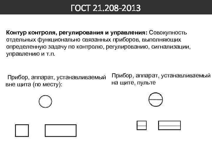 GOST 21. 208 -2013 Monitoring, regulation and control circuit: A set of individual functionally related devices that perform a specific task of monitoring, regulation, signaling, management, etc. Device, apparatus installed on a switchboard, remote control outside the switchboard (locally) :
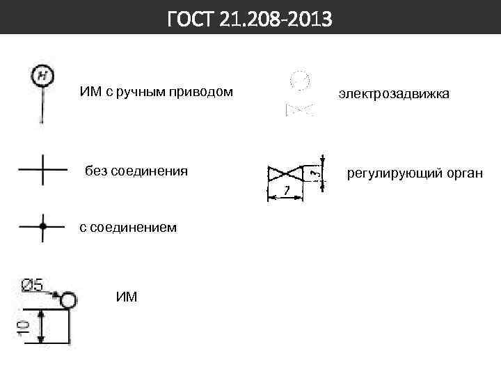 GOST 21.208 -2013 IM with manual drive without connection to the connection IM electric valve regulating body
 GOST 21.208 -2013 At the top of the graphic designation, letter designations of the measured quantity and the functional characteristic of the device that determine the purpose are applied. At the bottom of the graphic designation, a digital (positional) designation of a device or a set of automation equipment is applied.
 GOST 21. 208 -2013 Measured quantity: D - density, E - any electrical quantity, F - flow rate, G - position, movement, N - manual action, K - time program, L - level, M - humidity, P - pressure, Q - mixture composition, concentration, R - radioactivity, S - speed (linear or angular), T - temperature, U - heterogeneous quantities, V - viscosity, W - mass Additional designation of the measured quantity: D - difference, difference, F - ratio, J - automatic switching, Q - summation, integration
 GOST 21.208 -2013 Functions and functional features of the device: C – automatic control E – sensitive element G – primary indicating device I – secondary indicating device R – registration S – on, off, switching, blocking T – conversion Y – auxiliary computing device
 GOST 21.208 -2013 Primary measuring transducer for temperature measurement, installed locally. An indicating device for measuring temperature installed on a panel. A device for measuring temperature indicating, installed locally. A scaleless temperature measuring device with a contact device, installed locally. A single-point temperature measuring device, recording, installed on a panel. A device for measuring temperature with an automatic running device, recording, installed on a panel.
 GOST 21.208 -2013 Device for controlling the process according to a time program, installed on the panel. Primary measuring transducer (sensing element) for measuring product quality, installed on site. A computing device that performs a multiplication function. Starting equipment for controlling the electric motor (turning on and off the pump; opening and closing the valve, etc.). Equipment designed for manual remote control (turning on and off the engine; opening, closing a shut-off valve, changing the regulator’s task), installed on the switchboard.

 GOST 21.408 -2013 automated process control system; APCS: A set of software and hardware designed to automate the control of technological equipment at enterprises. embedded structure: A part or assembly unit that is permanently built into building structures (channel, angle, sleeve, pipe, plate with sleeves, boxes with sand gate, suspended ceiling structures, etc.), into equipment or communications (bosses, sleeves, fittings, pockets, expanders, flange connections, counter flanges, adapters, etc.). monitoring, regulation and control circuit: A set of separate functionally related technical automation equipment that perform a specific task of monitoring, regulation, signaling, management, etc.
 GOST 21.408 -2013 Contents of the main set of working drawings of automation systems: - general data on working drawings; - automation schemes; - schematic (electrical, pneumatic) diagrams; - diagrams (tables) of connections and connections of external wiring; - drawings of the location of equipment and external wiring; - drawings of automation equipment installations.

 GOST 21.408 -2013 The automation diagram shows: - technological and engineering equipment and communications of the automated object; - technical means of automation or control, regulation and control circuits: - communication lines between individual technical means of automation or circuits.
 GOST 21.408 -2013 Communication with the technological process, impulse pipe line Electric power supply line Electronic or electrical analog, digital or discrete signal transmission line Electronic or electrical analog, digital or discrete signal transmission line, intrinsically safe
 GOST 21. 408 -2013 Pipeline shut-off valves (GOST 2. 78570) Gate valve (valve) through passage Gate valve Three-way valve (valve) Rotary valve Valve, control valve through passage Valve through passage Check valve (non-return valve) through
 GOST 21.408 -2013 Automation diagrams are performed in two ways: - expanded, in which the composition and location of the technical means of automation of each monitoring and control circuit are shown on the diagram; - simplified, in which the diagram shows the main functions of the monitoring and control circuits (without highlighting the individual technical automation equipment included in them and indicating the location).
 GOST 21.408 -2013 Detailed method of implementing automation schemes Conventional graphic designation of devices built into technological communications Conventional graphic designation of devices installed on process equipment
 GOST 21.408 -2013 Detailed method of implementing automation schemes The remaining technical means of automation are in rectangles located at the bottom of the diagram. Order: devices local panels and consoles complexes of technical equipment Alphanumeric designations of devices are indicated at the bottom of the circle (square, rectangle) or on the right side of it, designations of electrical devices are indicated to the right of their conventional graphic designation.
 GOST 21.408 -2013 Detailed method of implementing automation schemes Communication lines can be depicted with a break if they are long and/or if their location is complex. Locations of communication line breaks are numbered with Arabic numerals in the order of their location in a rectangle with the heading “Local devices”. Intersection of communication lines with images of technological equipment is allowed. Intersection of communication lines with device designations is not allowed.

 GOST 21.408 -2013 A simplified way to implement automation circuits Monitoring and control circuits, as well as single devices, are placed next to the image of process equipment and communications (or in their gap). It is recommended to provide a table of circuits at the bottom of the diagram. The table of circuits indicates the circuit numbers and the sheet number of the main kit, which shows the composition of each circuit. The contour (regardless of the number of elements included in it) is depicted as a circle (rectangle) divided by a horizontal line. In the upper part of the circle, write a letter designation that defines the measured (adjustable) parameter and the functions performed by this circuit, in the lower part - the circuit number. For circuits of automatic control systems, in addition, the diagram shows actuators, control elements and a communication line connecting the circuits to the actuators.
 GOST 21.408 -2013 Circuit number 2 3 4, 5, 6 7 8 Sheet number 2 2 2
