This is a very important question. If there is an error in choosing a heating system the rooms will be cold, or expenses for heating will be completely unbearable.
DIY heating connection diagrams for a private house
Exists several types heating systems for a private home that you can do yourself.
Single pipe systems

Key element - boiler. In it, the coolant is heated, passes through the heating system and returns back to the boiler, where the water is heated again.
Serves as a cold water intake pipe second part of the system. The entire system is circular and closed in a continuous cycle.
Single-pipe systems are:
- Closed- does not communicate with the surrounding air, and if there is excess pressure inside, excess air is removed manually. The volume of liquid in the system is constant.
- Open- have a leaky expansion tank into which excess air is forced out. The pipes passing through the house are located above the heating devices (to displace air into the container).
It comes out of the water heating boiler one pipe and, sequentially running around all the radiators, returns back.
- low cost;
- the flow of water is directed at will;
- ease of installation;
- the system can be mounted under the wall or under the floor;
- use of any boiler(solid fuel, gas, electric);
- All elements of the system are connected to the distribution pipe.
- High cost.
- The water temperature decreases from one battery to another, and if there are many radiators connected, then the last one is already cold. To heat all the rooms, the heating temperature must be greatly increased, which entails additional costs.
- Running coolant requires high pressure, for which an additional pump is installed.
- High system pressure causes wear(a large number of leaks occur).
- A system that It has not been used for a long time and is difficult to start.
- Without installing the proper slope, air plugs may occur in the chain., which makes heat transfer difficult.
- It is not possible to repair a single link without shutting down the entire system.
Horizontal
The principle of operation is circulation through a closed horizontal coolant circuit, which enters and exits the same boiler.

Photo 1. Horizontal single-pipe heating system with a main pipe from which wiring goes to the batteries.
From the heating boiler, the main pipe is laid horizontally (on the floor or under the floor), from which branches are made to the radiators. If the house is two-story, then on the first floor a riser cuts into the main pipe to supply water to the second floor.
Attention! The main pipe is being laid on a slight slope(with natural coolant circulation), while the batteries should be installed at the same level.
If the structure is mounted on the floor, then the pipes are insulated so that there is no excess heat transfer.

- ease of installation;
- cheapness;
- if the system is equipped with bypasses, then the difference in temperature is small;
- dismantling one battery does not require shutting down the entire system;
- the coolant circulation will be quite fast.
- temperature adjustment on individual radiators is not possible;
- when repairing one link, the entire system must be stopped;
- The difference in temperature between the first and last radiator is very large.
The connection can be:
- Flow-through(severe heat loss, not recommended for small rooms).
- With bypasses(the bypass diameter should be smaller than that of the main pipe. Part of the water goes to the radiator, the rest moves further through the system).
- Nizhny(possibly with forced passage of liquid).
- Diagonal(better for heat transfer).
Important! If the system is mounted for a two-story house, then the equipment must include a pump for forced circulation of liquid.
You might also be interested in:
Vertical

All batteries in parallel connected to vertical risers. It is advisable to install this system in buildings with more than two storeys. The heated coolant flows from top to bottom.
The heated coolant supply from the boiler goes to the top of the tank and from there it diverges along the conductive line to the radiators. The cooled liquid is returned to the boiler.
- ease of installation;
- uniform heat distribution;
- when renovating one floor, it is not necessary to turn off the other;
- good natural current.
- high pipe consumption;
- heating large rooms is difficult.
Installation nuances:
- The presence of an expansion tank is mandatory here. Installed at the peak point (attic).
- It is advisable to install one Mayevsky crane on the floor.
- The main pipe is laid with a slight slope.
Only metal pipes can be attached to the boiler.
Project of the Leningradka scheme
The heated coolant leaves the heating boiler, sequentially passes through all connected heating devices and returns back.
"Leningradka" can be:
- vertical;
- horizontal;
- with top or bottom wiring.
The main pipe is being laid along the outer walls of the building, encircling it around the perimeter. All heating devices, including heated floors, are connected to this pipe. Allowed into the system inset of modern elements(pump, thermostatic valves, bypasses, etc.).

Photo 2. Diagram of the Leningradka heating system with a circulation pump, four radiators and an expansion tank.
- possibility of connecting several heating boilers;
- low cost;
- low pipe consumption.
- use of large diameter pipes so that the entire system works efficiently;
- Air locks often form in the system;
- to the system You can connect heated floors or a heated towel rail, but the power is not enough for full-fledged operation.
When assembling the system, the following points must be taken into account:
- If the main pipe is laid below floor level, then In addition, thermal insulation must be used to avoid overheating of the floor.
- The main pipe is pulled with a slight slope.
- The expansion tank must be installed close to the boiler.
- The pump can only be installed after the expansion tank along the flow of the coolant.
- Installation heating carried out before any finishing work begins.
- Radiators are located only on one level.
Important! Due to excessive airing of the chain, use Mayevsky cranes Necessarily.
During installation, sudden changes in height must be avoided, since in this case, traffic jams are guaranteed.
Two-pipe with bottom wiring

The main difference between this system and a single-pipe system is the number of pipes: hot water is supplied through one, and cold water is discharged through the other.
Both pipes(both supplying and collecting) are located below under the batteries. The hot coolant pipe is laid above the return pipe. The liquid moves through the system from bottom to top.
Exists two connection methods batteries:
- ray— each radiator is connected to the main pipe by separate connections;
- consistent.
The system can be installed with:
- passing contour(liquid in both pipes moves in the same direction);
- dead end(coolant moves in different directions);
- one;
- several.
- autonomy of floor heating;
- possibility of operation until the construction of the house is stopped;
- low heat loss due to installation features;
- the central unit can be placed in the basement.

- airiness systems - air bleeding must be carried out daily;
- when installing an overhead line system becomes unnecessarily bulky;
- high consumption of materials(especially for radial connection);
- adjustment should be carried out before the onset of cold weather;
- low pressure in the supply coolant.
When laying the chain, the following points must be taken into account:
- Radiators are additionally equipped with Mayevsky taps to remove air from the system (air vents can be installed).
- If the system is installed in a multi-story building, then laying an overhead line, through which excess air is discharged into the expansion tank.
- If the main pipe ends up near the front door during installation, it can be divided into 2 elbows.
Two-pipe with top wiring
This system is good in houses with several floors. The heated coolant under pressure goes from bottom to top into the tank, and from there through the supply pipe to the radiators. A system with top supply is always vertical; heating radiators are mounted parallel to vertical risers.
The supply pipe runs through the attic or tech. floor, and the return pipe - in the basement or below floor level on the first floor.

Photo 3. The diagram of a two-pipe heating system with overhead wiring is suitable for private houses with two or more floors.
- ease of installation;
- low heat loss;
- airiness does not occur;
- excellent natural circulation.
- it will not be possible to install a large number of radiators;
- high consumption of components;
- does not heat a large area.
The chain is mounted taking into account three points:
- mandatory installation of an expansion tank at the top point of the supply pipe;
- if the coolant flow is natural, then a slight slope is taken into account when laying both pipes;
- the supply pipe goes to the batteries through the expansion tank.
Beam system with collectors
A collector is connected to the heating boiler - single thermal unit, from which each radiator in the room has its own branch. The collector is:
- simple;
- improved(with automatic temperature control).

This option is suitable for a two-story house. Departs from the collector from two to twelve knots- depending on the number of radiators in the house. If necessary, the number of layers is increased.
To the collector "comb" you can connect a pump- for forced circulation of liquid. And hide the structure itself in a closet so as not to spoil the aesthetics of the house.
- durability;
- ease of repair(no need to disconnect the entire circuit);
- temperature adjustment;
- uniform temperature in all rooms.
- price.
Reference! To somehow reduce the cost of pipes, it is better to install a manifold cabinet in the central part of the house.
Installation nuances:
- Typically, this system uses metal-plastic pipes. When installing in the floor, it is recommended to wrap each pipe in insulation so as not to injure it on the concrete during expansion.
- Recommended diameter is 16 mm.
- Do not route pipes through doorways- otherwise the pipe may be damaged when drilling.
- When laying through walls, it is recommended to install them in cartridges.
You might also be interested in:
With forced circulation

The built-in pump ensures rapid circulation of liquid in the system, which reduces heat loss along the path.
Increased speed prevents mixing of hot and cold water - the temperature in all rooms is equal.
By adjusting the flow rate of the coolant, the temperature in the room is controlled.
According to the project, a pump is built into the forced circulation system to accelerate the coolant.
- comfortable operation;
- possibility of choosing a mounted circuit(collector, one-, two-pipe);
- heating adjustment;
- increasing the service life of components;
- installation of pipes of smaller cross-section.
- pumping system increases initial installation costs;
- noise from a running pump;
- additional electricity costs.
Installation nuances:
Place of installation of the pump group depends on the method of pipe routing. Thanks to the artificial pressure inside the system, the slope is not installed.
With natural circulation

The liquid in the system, heating up, rises and goes into the radiators, where the coolant cools. The cold liquid sinks down. Pressure depends from the temperature difference. The cycle is closed.
- The boiler is installed below the level of the radiators.
- Branch pipes are smaller in diameter than the main pipe.
- A diagonal connection would be correct., in which hot water enters the radiator from above.
- To improve fluid circulation a slight slope is provided.
Install an expansion tank: if there is excess pressure, some of the liquid will flow into it, and if it falls, it will return back into the system.
- low cost;
- Possibility of installation of one- or two-pipe systems to choose from;
- easy repairs;
- does not clutter up the space;
- reliability;
- long service life.
Available only in single-pipe natural circulation systems:
- Uneven heat distribution: in rooms located closer to the boiler it is hot, in rooms further away it is cold.
- Additional expenses: To increase the temperature in cool rooms, batteries are built up or powerful radiators are installed.
- Increased fuel consumption(compared to pump type).

Installation nuances:
- Overheating protection is built into the circuit to prevent airing.
- Each radiator is equipped with a bypass, a thermostat and a Mayevsky tap.
In natural circulation circuits, only water is used (due to its density, antifreeze is not suitable).
Useful video
Watch a video review of a two-pipe heating system, connection options, pros and cons.
Readers.
You can purchase an arbitrarily powerful heating boiler, but still not achieve the expected warmth and comfort in your home. The reason for this may well be incorrectly selected final heat exchange devices indoors, as which are traditionally most often radiators. But even assessments that seem to be quite suitable according to all criteria sometimes do not meet the expectations of their owners. Why?
And the reason may lie in the fact that the radiators were connected according to a scheme that is very far from optimal. And this circumstance simply does not allow them to show those output heat transfer parameters that are announced by manufacturers. Therefore, let's take a closer look at the question: what are the possible connection diagrams for heating radiators in a private house. Let's see what the advantages and disadvantages of certain options are. Let's see what technological techniques are used to optimize some circuits.
Necessary information for choosing the right radiator connection diagram
In order to make further explanations more understandable to the inexperienced reader, it makes sense to first consider what a standard heating radiator is, in principle. The term “standard” is used because there are also completely “exotic” batteries, but the plans of this publication do not include their consideration.
Basic design of a heating radiator
So, if you depict a regular heating radiator schematically, you might get something like this:

From a layout point of view, this is usually a set of heat exchange sections (item 1). The number of these sections can vary over a fairly wide range. Many battery models allow you to vary this amount, adding or decreasing, depending on the required thermal total power or based on the maximum permissible dimensions of the assembly. To do this, a threaded connection is provided between the sections using special couplings (nipples) with the necessary sealing. Other radiators do not have this possibility; their sections are tightly connected or even form a single metal structure. But in the light of our topic, this difference is not of fundamental importance.
But what is important is the hydraulic part of the battery, so to speak. All sections are united by common collectors located horizontally at the top (item 2) and bottom (item 3). And at the same time, each section provides for the connection of these collectors with a vertical channel (item 4) for the movement of coolant.
Each of the collectors has two inputs, respectively. In the diagram they are designated G1 and G2 for the upper collector, G3 and G4 for the lower.
In the vast majority of connection schemes used in heating systems of private houses, only these two inputs are always used. One is connected to the supply pipe (that is, coming from the boiler). The second is to the “return”, that is, to the pipe through which the coolant returns from the radiator to the boiler room. The remaining two entrances are blocked by plugs or other locking devices.
And what’s important is that the efficiency of the expected heat transfer of the heating radiator largely depends on how these two inputs, supply and return, are mutually located.
Note : Of course, the diagram is given with a significant simplification, and many types of radiators may have their own characteristics. So, for example, in the familiar MS-140 cast iron batteries, each section has two vertical channels connecting the collectors. And in steel radiators there are no sections at all - but the system of internal channels, in principle, repeats the hydraulic circuit shown. So everything that will be said below applies equally to them.
Where is the supply pipe and where is the return pipe?
It is quite clear that in order to correctly optimally position the inlet and outlet to the radiator, it is necessary to at least know in which direction the coolant is moving. In other words, where is the supply and where is the “return”. And the fundamental difference may be hidden in the type of heating system itself - it can be single-pipe or
Features of a single-pipe system
This heating system is especially common in high-rise buildings; it is also quite popular in single-story individual construction. Its wide demand is primarily based on the fact that significantly fewer pipes are required during creation, and the volume of installation work is reduced.
To explain it as simply as possible, this system is one pipe running from the supply pipe to the inlet pipe of the boiler (as an option - from the supply to the return manifold), onto which series-connected heating radiators seem to be “strung”.
On the scale of one level (floor) it might look something like this:

It is quite obvious that the “return” of the first radiator in the “chain” becomes the supply of the next one - and so on, until the end of this closed circuit. It is clear that from the beginning to the end of a single-pipe circuit, the coolant temperature steadily decreases, and this is one of the most significant disadvantages of such a system.
It is also possible to arrange a single-pipe circuit, which is typical for buildings with several floors. This approach was usually practiced in the construction of urban apartment buildings. However, you can also find it in private houses with several floors. This should also not be forgotten if, say, the owners got the house from the old owners, that is, with the heating circuits already installed.
There are two possible options here, shown below in the diagram under the letters “a” and “b”, respectively.
Prices for popular heating radiators

- Option “a” is called a riser with top coolant supply. That is, from the supply manifold (boiler), the pipe rises freely to the highest point of the riser, and then sequentially passes down through all the radiators. That is, the supply of hot coolant directly to the batteries is carried out in the direction from top to bottom.
- Option “b” - single-pipe distribution with bottom feed. Already on the way up, along the ascending pipe, the coolant passes a series of radiators. Then the flow direction changes to the opposite, the coolant passes through another string of batteries until it enters the “return” collector.
The second option is used for reasons of saving pipes, but it is obvious that the disadvantage of a single-pipe system, that is, the temperature drop from radiator to radiator along the coolant flow, is expressed to an even greater extent.
Thus, if you have a single-pipe system installed in your house or apartment, then in order to select the optimal radiator connection diagram, you should definitely clarify in which direction the coolant is supplied.
Secrets of the popularity of the Leningradka heating system
Despite quite significant disadvantages, single-pipe systems still remain quite popular. An example of this is described in detail in a separate article on our portal. And another publication is devoted to that element without which single-pipe systems are not able to operate normally.
What if the system is two-pipe?
A two-pipe heating system is considered more advanced. It is easier to operate and lends itself better to fine adjustments. But this is against the backdrop of the fact that more material will be required to create it, and installation work is becoming more extensive.

As can be seen from the illustration, both the supply and return pipes are essentially collectors to which the corresponding pipes of each radiator are connected. An obvious advantage is that the temperature in the supply pipe-collector is maintained almost the same for all heat exchange points, that is, it almost does not depend on the location of a particular battery in relation to the heat source (boiler).
This scheme is also used in systems for houses with several floors. An example is shown in the diagram below:

In this case, the supply riser is plugged from above, as is the return pipe, that is, they are turned into two parallel vertical collectors.
It is important to understand one nuance correctly here. The presence of two pipes near the radiator does not mean that the system itself is two-pipe. For example, with a vertical layout there may be a picture like this:

This arrangement can mislead an owner who is inexperienced in these matters. Despite the presence of two risers, the system is still single-pipe, since the heating radiator is connected to only one of them. And the second is a riser that provides the upper supply of coolant.
Prices for aluminum radiators
aluminum radiator
It's a different matter if the connection looks like this:

The difference is obvious: the battery is embedded in two different pipes - supply and return. That is why there is no bypass jumper between the inputs - it is completely unnecessary with such a scheme.
There are other two-pipe connection schemes. For example, the so-called collector (it is also called “radial” or “star”). This principle is often resorted to when they try to place all the circuit distribution pipes secretly, for example, under the floor covering.

In such cases, a collector unit is placed in a certain place, and from It already has separate supply and return pipes for each of the radiators. But at its core, it is still a two-pipe system.
Why is all this being said? And besides, if the system is two-pipe, then to select a radiator connection diagram it is important to clearly know which of the pipes is the supply manifold and which is connected to the “return”.
But the direction of flow through the pipes themselves, which was decisive in a single-pipe system, no longer plays a role here. The movement of the coolant directly through the radiator will depend solely on the relative position of the tie-in pipes into the supply and return.
By the way, even in a small house, a combination of both schemes can be used. For example, a two-pipe system is used, however, in a separate area, say, in one of the spacious rooms or in an extension, several radiators connected according to the single-pipe principle are placed. This means that when choosing a connection diagram, it is important not to get confused, and to individually evaluate each heat exchange point: what will be decisive for it - the direction of flow in the pipe or the relative position of the supply and return collector pipes.
If such clarity is achieved, you can select the optimal scheme for connecting radiators to the circuits.
Diagrams for connecting radiators to the circuit and assessing their effectiveness
Everything said above was a kind of “prelude” to this section. Now we will get acquainted with how you can connect radiators to the pipes of the circuit, and which method provides maximum heat transfer efficiency.
As we have already seen, two radiator inputs are activated, and two more are muted. What direction of movement of the coolant through the battery will be optimal?
A few more preliminary words. What are the “motivating reasons” for the movement of coolant through the radiator channels.
- This is, firstly, the dynamic fluid pressure created in the heating circuit. The liquid tends to fill the entire volume if conditions are created for this (there are no air pockets). But it is quite clear that, like any flow, it will tend to flow along the path of least resistance.
- Secondly, the difference in temperature (and, accordingly, density) of the coolant in the radiator cavity itself becomes the “driving force”. Hotter flows tend to rise, trying to displace cooler ones.
The combination of these forces ensures the flow of coolant through the radiator channels. But depending on the connection diagram, the overall picture can vary quite a bit.
Prices for cast iron radiators
cast iron radiator
Diagonal connection, top feed
This scheme is considered to be the most effective. Radiators with such a connection show their full capabilities. Usually, when calculating a heating system, it is this that is taken as the “unit”, and for all the others one or another correction reduction factor will be introduced.

It is quite obvious that a priori the coolant cannot encounter any obstacles with such a connection. The liquid completely fills the volume of the upper manifold pipe and flows evenly through vertical channels from the upper to the lower manifold. As a result, the entire heat exchange area of the radiator is heated evenly, and maximum heat transfer from the battery is achieved.
Single-sided connection, top feed
Very widespread diagram - this is how radiators are usually installed in a single-pipe system in the risers of high-rise buildings with top supply, or on descending branches with bottom supply.

In principle, the circuit is quite effective, especially if the radiator itself is not too long. But if there are many sections assembled into a battery, then the appearance of negative aspects cannot be ruled out.
It is quite likely that the kinetic energy of the coolant will be insufficient for the flow to fully pass through the upper collector to the very end. The liquid looks for “easy paths”, and the bulk of the flow begins to pass through the vertical internal channels of the sections, which are located closer to the inlet pipe. Thus, it is impossible to completely exclude the formation of a stagnation area in the “peripheral zone”, the temperature of which will be lower than in the area adjacent to the side of the cut-in.
Even with normal radiator sizes along the length, you usually have to put up with a loss of thermal power of approximately 3–5%. Well, if the batteries are long, then the efficiency may be even lower. In this case, it is better to use either the first scheme, or use special methods for optimizing the connection - a separate section of the publication will be devoted to this.
Single-sided connection, bottom feed
The scheme cannot be called effective, although, by the way, it is used quite often when installing single-pipe heating systems in multi-storey buildings, if the supply is from below. On the ascending branch, builders will most often install all the batteries in the riser this way. and, probably, this is the only at least somewhat justified case of its use.

Despite all the similarities with the previous one, the shortcomings here only get worse. In particular, the occurrence of a stagnation zone on the side of the radiator away from the inlet becomes even more likely. This is easy to explain. Not only will the coolant look for the shortest and freest path, but the difference in density will also contribute to its upward movement. And the periphery may either “freeze” or the circulation in it will be insufficient. That is, the far edge of the radiator will become noticeably colder.
Losses in heat transfer efficiency with such a connection can reach 20÷22%. That is, it is not recommended to resort to it unless absolutely necessary. And if circumstances leave no other choice, then it is recommended to resort to one of the optimization methods.
Two-way bottom connection
This scheme is used quite often, usually for reasons of hiding the supply pipe from visibility as much as possible. True, its effectiveness is still far from optimal.

It is quite obvious that the easiest path for coolant is the lower collector. Its spread upward through vertical channels occurs solely due to the difference in density. But this flow is hindered by counter flows of cooled liquid. As a result, the upper part of the radiator can warm up much more slowly and not as intensely as we would like.
Losses in the overall efficiency of heat exchange with such a connection can reach up to 10÷15%. True, such a scheme is also easy to optimize.
Diagonal connection with bottom feed
It is difficult to think of a situation in which one would be forced to resort to such a connection. Nevertheless, let's consider this scheme.
Prices for bimetallic radiators
bimetallic radiators

The direct flow entering the radiator gradually wastes its kinetic energy, and may simply not “finish” along the entire length of the lower collector. This is facilitated by the fact that the flows in the initial section rush upward, both along the shortest path and due to the temperature difference. As a result, on a battery with large comic sections, it is quite likely that a stagnant area with a low temperature will appear under the return pipe.
Approximate loss of efficiency, despite the apparent similarity with the most optimal option, with such a connection are estimated at 20%.
Two-way connection from above
Let's be honest - this is more for an example, since applying such a scheme in practice would be the height of illiteracy.

Judge for yourself - a direct passage through the upper manifold is open for liquid. And generally no other incentives for spreading throughout the rest of the radiator volume. That is, only the area along the upper collector will actually heat up - the rest of the area is “outside the game”. It is hardly worth assessing the loss of efficiency in this case - the radiator itself becomes clearly ineffective.
The upper two-way connection is rarely used. Nevertheless, there are also such radiators - distinctly high ones, often simultaneously serving as dryers. And if you have to connect pipes this way, then it is imperative to use various methods to transform such a connection into an optimal scheme. Very often this is already built into the design of the radiators themselves, that is, the top one-sided connection remains so only visually.
How can you optimize the radiator connection diagram?
It is quite understandable that any owners want their heating system to show maximum efficiency with minimal energy consumption. And for this we must try to apply the most optimal insert diagrams. But often the pipework is already there and you don’t want to redo it. Or, initially, the owners plan to lay the pipes so that they become almost invisible. What to do in such cases?
On the Internet you can find many photographs where they try to optimize the insert by changing the configuration of the pipes suitable for the battery. The effect of increasing heat transfer must be achieved, but outwardly some works of such “art” look, frankly, “not very good.”

There are other methods to solve this problem.
- You can purchase batteries that, although outwardly no different from ordinary ones, still have a feature in their design that turns one or another possible connection method into one as close to optimal as possible. A partition is installed in the right place between the sections, which radically changes the direction of movement of the coolant.
In particular, the radiator can be designed for bottom two-way connection:

All the “wisdom” is the presence of a partition (plug) in the lower collector between the first and second sections of the battery. The coolant has nowhere to go, and it rises vertical channel of the first section up. And then, from this upper point, further distribution, quite obviously, already proceeds, as in the most optimal diagram with a diagonal connection with supply from above.
Or, for example, the case mentioned above, when both pipes need to be brought from above:

In this example, the baffle is installed on the upper manifold, between the penultimate and last sections of the radiator. It turns out that there is only one path left for the entire volume of coolant - through the lower entrance of the last section, vertically along it - and then into the return pipe. Eventually " route The fluid flow through the battery channels again becomes diagonal from top to bottom.
Many radiator manufacturers think through this issue in advance - whole series go on sale in which the same model can be designed for different insertion patterns, but in the end the optimal “diagonal” is obtained. This is indicated in the product data sheets. At the same time, it is also important to take into account the direction of the insertion - if you change the flow vector, the entire effect is lost.
- There is another possibility to increase the efficiency of the radiator using this principle. To do this, you should find special valves in specialized stores.

They must correspond in size to the selected battery model. When such a valve is screwed in, it closes the transition nipple between the sections, and then the supply or “return” pipe is packed into its internal thread, depending on the design.
- The internal partitions shown above are intended primarily to improve heat transfer when batteries are connected on both sides. But there are ways for one-way insertion - we are talking about so-called flow extenders.

Such an extension is a pipe, usually with a nominal diameter of 16 mm, which is connected to the radiator plug and, when assembled, ends up in the cavity of the manifold, along its axis. On sale you can find such extensions for the required type of thread and the required length. Or you can simply purchase a special coupling, and select a tube of the required length for it separately.

Prices for metal-plastic pipes
metal-plastic pipes
What does this achieve? Let's look at the diagram:

The coolant entering the radiator cavity travels through the flow extension to the far upper corner, that is, to the opposite edge of the upper manifold. And from here its movement to the outlet pipe will again be carried out according to the optimal “diagonal from top to bottom” pattern.
Many masters They also practice making their own extension cords. If you look at it, there is nothing impossible about it.

As the extension cord itself, it is quite possible to use a metal-plastic pipe for hot water with a diameter of 15 mm. All that remains is to pack the fitting for the metal plastic from the inside into the passage plug of the battery. After assembling the battery, the extension cord of the required length is put into place.
As can be seen from the above, it is almost always possible to find a solution on how to turn an ineffective battery insertion scheme into an optimal one.
What can you say about the one-way bottom connection?
They may ask in bewilderment - why the article has not yet mentioned the diagram of the lower connection of the radiator on one side? After all, it enjoys quite wide popularity, since it allows for hidden pipe connections to the maximum extent.
But the fact is that the possible schemes were considered above, so to speak, from a hydraulic point of view. And in them series of one-way bottom connection there is simply no space - if at one point both the coolant is supplied and taken away, then no flow through the radiator will occur at all.
What is commonly understood under the bottom one-sided connection in fact, it only involves connecting pipes to one edge of the radiator. But the further movement of the coolant through the internal channels, as a rule, is organized according to one of the optimal schemes discussed above. This is achieved either by the design features of the battery itself, or by special adapters.
Here is just one example of radiators specifically designed for piping On the one side below:

If you look at the diagram, it immediately becomes clear that the system of internal channels, partitions and valves organizes the movement of the coolant according to the already known principle of “one-way with supply from above,” which can be considered one of the optimal options. There are similar schemes that are also supplemented with a flow extender, and then the most effective “diagonal from top to bottom” pattern is generally achieved.
Even an ordinary radiator can be easily converted into a model with a bottom connection. To do this, purchase a special kit - a remote adapter, which, as a rule, is immediately equipped with thermal valves for thermostatic adjustment of the radiator.

The upper and lower pipes of such a device are packed into the sockets of a conventional radiator without any modifications. The result is a finished battery with a bottom one-sided connection, and even with a thermal regulation and balancing device.
So, we figured out the connection diagrams. But what else can affect the heat transfer efficiency of a heating radiator?
How does its location on the wall affect the efficiency of the radiator?
You can purchase a very high-quality radiator, apply the optimal connection diagram, but in the end you will not achieve the expected heat transfer, if you do not take into account a number of important nuances of its installation.
There are several generally accepted rules for the location of batteries in a room relative to the wall, floor, window sills, and other interior items.
- Most often, radiators are located under window openings. This place is still unclaimed for other objects, and besides this, the flow of heated air becomes a kind of thermal curtain, which largely limits the free spread of cold from the surface of the window.
Of course, this is just one of the installation options, and radiators can also be mounted on walls, regardless of the presence of those window openings– it all depends on the required number of such heat exchange devices.

- If the radiator is installed under a window, then they try to adhere to the rule that its length should be about ¾ the width of the window. This will ensure optimal heat transfer and protection against the penetration of cold air from the window. The battery is installed in the center, with a possible tolerance of up to 20 mm in one direction or another.
- The radiator should not be installed too high - a window sill hanging over it can turn into an insurmountable barrier to rising convection air currents, which leads to a decrease in the overall efficiency of heat transfer. They try to maintain a clearance of about 100 mm (from the top edge of the battery to the bottom surface of the “visor”). If you can’t set the entire 100 mm, then at least ¾ of the radiator thickness.
- There is a certain regulation of clearance from below, between the radiator and the floor surface. A position that is too high (more than 150 mm) can lead to the formation of a layer of air along the floor covering that is not involved in convection, that is, a noticeably cold layer. Too small a height, less than 100 mm, will introduce unnecessary difficulties during cleaning; the space under the battery can turn into an accumulation of dust, which, by the way, will also negatively affect the efficiency of thermal output. The optimal height is within 100÷120 mm.
- The optimal location from the load-bearing wall should also be maintained. Even when installing brackets for the battery canopy, take into account that there must be a free gap of at least 20 mm between the wall and the sections. Otherwise, dust deposits may accumulate there and normal convection will be disrupted.
These rules can be considered indicative. If the radiator manufacturer does not give other recommendations, then you should follow them. But quite often, the passports of specific battery models contain diagrams that specify the recommended installation parameters. Of course, then they are taken as the basis for installation work.

The next nuance is how open the installed battery is for complete heat exchange. Of course, the maximum performance will be with a completely open installation on a flat vertical wall surface. But, quite understandably, this method is not used so often.

If the battery is located under a window, then the window sill may interfere with the convection air flow. The same thing, even to a greater extent, applies to niches in the wall. In addition, they often try to cover radiators, or even completely closed them (with the exception of the front grille) with casings. If these nuances are not taken into account when choosing the required heating power, that is, the thermal output of the battery, then you may well be faced with the sad fact that it is not possible to achieve the expected comfortable temperature.

The table below shows the main possible options for installing radiators on the wall according to their “degree of freedom”. Each case is characterized by its own indicator of loss of overall heat transfer efficiency.
| Illustration | Operational features of the installation option |
|---|---|
 | The radiator is installed so that nothing overlaps the top, or the window sill (shelf) protrudes no more than ¾ of the thickness of the battery. In principle, there are no obstacles to normal air convection. If the battery is not covered with thick curtains, then there is no interference with direct thermal radiation. In calculations, this installation scheme is taken as a unit. |
 | The horizontal “visor” of a window sill or shelf completely covers the radiator from above. That is, a rather significant obstacle appears to the ascending convection flow. With normal clearance (which was already mentioned above - about 100 mm), the obstacle does not become “fatal”, but certain losses in efficiency are still observed. Infrared radiation from the battery remains in full. The final loss of efficiency can be estimated at approximately 3÷5%. |
 | A similar situation, but only on top there is not a canopy, but a horizontal wall of a niche. Here the losses are already somewhat greater - in addition to simply the presence of an obstacle to the air flow, some of the heat will be spent on unproductive heating of the wall, which usually has a very impressive heat capacity. Therefore, it is quite possible to expect heat losses of approximately 7 - 8%. |
 | The radiator is installed as in the first option, that is, there are no obstacles to convection flows. But on the front side, its entire area is covered with a decorative grille or screen. The intensity of infrared heat flow is significantly reduced, which, by the way, is the determining principle of heat transfer for cast iron or bimetallic batteries. The overall loss of heating efficiency can reach 10÷12%. |
 | A decorative casing covers the radiator on all sides. Despite the presence of slits or grilles to ensure heat exchange with the air in the room, both thermal radiation and convection are sharply reduced. Therefore, we have to talk about a loss of efficiency reaching 20–25%. |
So, we examined the basic schemes for connecting radiators to the heating circuit, and analyzed the advantages and disadvantages of each of them. Information was obtained on the methods used to optimize circuits if, for some reason, it is impossible to change them in other ways. Finally, recommendations are provided for placing batteries directly on the wall - indicating the risks of loss of efficiency that accompany selected installation options.
Presumably, this theoretical knowledge will help the reader choose the right scheme based on from the specific conditions for creating a heating system. But it would probably be logical to end the article by providing our visitor with the opportunity to independently evaluate the required heating battery, so to speak, in numerical terms, with reference to a specific room and taking into account all the nuances discussed above.
There is no need to be scared - all this will be easy if you use the offered online calculator. Below you will find the necessary brief explanations for working with the program.
How to calculate which radiator is needed for a particular room?
Everything is quite simple.
- First, the amount of thermal energy required to warm up the room is calculated, depending on its volume, and to compensate for possible heat losses. Moreover, a fairly impressive list of diverse criteria is taken into account.
- Then the obtained value is adjusted depending on the planned radiator insertion pattern and the features of its location on the wall.
- The final value will show how much power a radiator needs to fully heat a particular room. If you purchase a collapsible model, then you can at the same time
Properly organizing home heating is not an easy task. It is clear that specialists - designers and installers - can handle it best. It is possible and necessary to involve them in the process, but in what capacity is up to you, the owner of the house, to determine. There are three options: hired people perform the entire range of activities or part of these works, or act as consultants, and you do the heating yourself.
Regardless of which heating option is chosen, you need to have a good understanding of all stages of the process. This material is a step-by-step guide to action. Its goal is to help you solve the problem of installing heating yourself or competently supervise hired specialists and installers.
Heating system elements
In the vast majority of cases, private residential buildings are heated with water heating systems. This is a traditional approach to solving the issue, which has an undeniable advantage - universality. That is, heat is delivered to all rooms through a coolant, and it can be heated using various energy carriers. We will consider their list further when choosing a boiler.
Water systems also make it possible to organize combined heating using two or even three types of energy carriers.
Any heating system, where the coolant serves as the transfer link, is divided into the following components:
- heat source;
- pipeline network with all additional equipment and fittings;
- heating devices (radiators or underfloor heating circuits).
For the purpose of processing and regulating the coolant, as well as performing maintenance work in heating systems, additional equipment and shut-off and control valves are used. The equipment includes the following items:
- expansion tank;
- circulation pump;
- hydraulic separator (hydraulic arrow);
- buffer capacity;
- distribution manifold;
- indirect heating boiler;
- devices and automation equipment.
Note. A mandatory attribute of a water heating system is an expansion tank, the rest of the equipment is installed as needed.
It is well known that when heated, water expands, and in a confined space there is nowhere for its additional volume to go. To avoid rupture of connections due to increased pressure in the network, an open or membrane type expansion tank is installed. She takes in excess water.
Forced circulation of the coolant is provided by a pump, and if there are several circuits separated by a hydraulic arrow or a buffer tank, 2 or more pumping units are used. As for the buffer tank, it works simultaneously as a hydraulic separator and a heat accumulator. Separating the boiler circulation circuit from all others is practiced in complex systems of cottages with several floors.
Collectors for coolant distribution are installed in heating systems with heated floors or in cases where a radial battery connection scheme is used, we will discuss this in the following sections. An indirect heating boiler is a tank with a coil where water for domestic hot water needs is heated from the coolant. To visually monitor the temperature and pressure of water in the system, thermometers and pressure gauges are installed. Automation tools (sensors, thermostats, controllers, servos) not only control the parameters of the coolant, but also regulate them automatically.
Shut-off valves
In addition to the equipment listed, the water heating of the house is controlled and maintained using shut-off and control valves shown in the table:
Once you have become familiar with what elements the heating system consists of, you can proceed to the first step towards the goal - calculations.
Calculation of the heating system and selection of boiler power
It is impossible to select equipment without knowing the amount of thermal energy required to heat the building. It can be determined in two ways: simple approximate and calculated. All sellers of heating equipment like to use the first method, since it is quite simple and gives a more or less correct result. This is a calculation of thermal power based on the area of heated premises.
They take a separate room, measure its area and multiply the resulting value by 100 W. The energy required for the entire country house is determined by summing up the indicators for all rooms. We suggest a more accurate method:
- by 100 W, multiply the area of those premises where only 1 wall, on which there is 1 window, is in contact with the street;
- if the room is a corner one with one window, then its area must be multiplied by 120 W;
- when a room has 2 external walls with 2 or more windows, its area is multiplied by 130 W.
If we consider power as an approximate method, then residents of the northern regions of the Russian Federation may not receive enough heat, and residents of the south of Ukraine may overpay for equipment that is too powerful. Using the second, calculation method, heating design is carried out by specialists. It is more accurate, as it gives a clear understanding of how much heat is lost through the building structures of any building.
Before you begin the calculations, you need to measure the house, finding out the area of the walls, windows and doors. Then you need to determine the thickness of the layer of each building material from which the walls, floors and roofs are built. For all materials in the reference literature or on the Internet, you should find the value of thermal conductivity λ, expressed in units of W/(m ºС). We substitute it into the formula for calculating the thermal resistance R (m2 ºС / W):
R = δ / λ, here δ is the thickness of the wall material in meters.
Note. When a wall or roof is made of different materials, it is necessary to calculate the R value for each layer and then sum the results.
Now you can find out the amount of heat lost through the external building structure using the formula:
- QTP = 1/R x (tв – tн) x S, where:
- QТП – lost amount of heat, W;
- S is the previously measured area of the building structure, m2;
- tв – here you need to substitute the value of the desired internal temperature, ºС;
- tн – street temperature in the coldest period, ºС.
Important! The calculation should be made for each room separately, alternately substituting into the formula the values of thermal resistance and area for the external wall, window, door, floors and roof. Then all these results must be summed up, this will be the heat loss of the given room. The areas of internal partitions do not need to be taken into account!
Heat consumption for ventilation
To find out how much heat a private house loses as a whole, you need to add up the losses of all its rooms. But that’s not all, because we must also take into account the heating of the ventilation air, which is also provided by the heating system. In order not to go into the jungle of complex calculations, it is proposed to find out this heat consumption using a simple formula:
Qair = cm (tв – tн), where:
- Qair – required amount of heat for ventilation, W;
- m is the amount of air by mass, defined as the internal volume of the building multiplied by the density of the air mixture, kg;
- (tв – tн) – as in the previous formula;
- с – heat capacity of air masses, is taken equal to 0.28 W / (kg ºС).
To determine the heat demand for the entire building, it remains to add the value of QTP for the house as a whole with the value of Qair. The boiler power is taken with a reserve for the optimal operating mode, that is, with a coefficient of 1.3. Here you need to take into account an important point: if you plan to use a heat generator not only for heating, but also for heating water for domestic hot water supply, then the power reserve must be increased. The boiler must operate effectively in 2 directions at once, and therefore the safety factor must be taken at least 1.5.
At the moment, there are various types of heating, characterized by the energy carrier or type of fuel used. Which one to choose is up to you, and we will present all types of boilers with a brief description of their pros and cons. To heat residential buildings, you can purchase the following types of household heat generators:
- solid fuel;
- gas;
- electrical;
- on liquid fuel.
The following video will help you choose an energy carrier, and then a heat source:
Solid fuel boilers
They are divided into 3 types: direct combustion, pyrolysis and pellet. The units are popular due to their low operating costs, because compared to other energy sources, firewood and coal are inexpensive. The exception is natural gas in the Russian Federation, but connecting to it is often more expensive than all the heating equipment including installation. Therefore, wood and coal boilers, which have an acceptable cost, are being purchased by people more and more often.
On the other hand, operating a solid fuel heat source is very similar to simple stove heating. You need to spend time and effort to prepare, carry firewood and load it into the firebox. The unit also requires serious piping to ensure its long-lasting and safe operation. After all, a conventional solid fuel boiler is characterized by inertia, that is, after closing the air damper, the heating of water does not stop immediately. And efficient use of generated energy is possible only with a heat accumulator.
Important. Boilers that burn solid fuels generally cannot boast of high efficiency. Traditional direct combustion units have an efficiency of about 75%, pyrolysis units - 80%, and pellet units - no more than 83%.
The best choice in terms of comfort is a pellet heat generator, characterized by a high level of automation and virtually no inertia. It does not require a heat accumulator and frequent trips to the boiler room. But the price of equipment and pellets often makes it inaccessible to a wide range of users.
Gas boilers
An excellent option is to install heating that operates on main gas. In general, hot water gas boilers are very reliable and efficient. The efficiency of the simplest energy-independent unit is at least 87%, and the efficiency of an expensive condensing unit is up to 97%. The heaters are compact, well automated and safe to operate. Maintenance is required no more than once a year, and trips to the boiler room are needed only to monitor or change settings. A budget unit will be much cheaper than a solid fuel unit, so gas boilers can be considered generally available.
Just like solid fuel heat generators, gas boilers require a chimney and supply and exhaust ventilation. As for other countries of the former USSR, the cost of fuel there is much higher than in the Russian Federation, which is why the popularity of gas equipment is steadily declining.
Electric boilers
It must be said that electric heating is the most efficient of all existing ones. Not only are the efficiency of boilers about 99%, but in addition they do not require chimneys or ventilation. There is practically no maintenance of the units as such, except for cleaning once every 2-3 years. And most importantly: equipment and installation are very cheap, and the degree of automation can be any. The boiler simply does not need your attention.
No matter how pleasant the advantages of an electric boiler are, the main disadvantage is just as significant - the price of electricity. Even if you use a multi-tariff electricity meter, you will not be able to beat a wood-burning heat generator in terms of this indicator. This is the price to pay for comfort, reliability and high efficiency. Well, the second disadvantage is the lack of the necessary electrical power on the supply networks. Such an annoying nuisance can immediately cancel out all thoughts about electric heating.
Liquid fuel boilers
In terms of the cost of heating equipment and its installation, heating with waste oil or diesel fuel will cost approximately the same as with natural gas. Their efficiency indicators are also similar, although the processing, for obvious reasons, is somewhat inferior. Another thing is that this type of heating can easily be called the dirtiest. Any visit to the boiler room will end with at least the smell of diesel fuel or dirty hands. And the annual cleaning of the unit is a whole event, after which you will be smeared with soot up to your waist.
Using diesel fuel for heating is not the most profitable solution; the price of fuel can hit your pocket hard. Used oil has also risen in price, unless you have some cheap source. This means that it makes sense to install a diesel boiler when there are no other energy sources or, in the future, a main gas supply. The unit easily switches from diesel fuel to gas, but the exhaust furnace will not be able to burn methane.
Heating system diagrams for a private home
Heating systems sold in private housing construction can be single-pipe or double-pipe. It's easy to distinguish them:
- According to a single-pipe scheme, all radiators are connected to one collector. It is both a supply and a return, passing by all the batteries in the form of a closed ring;
- in a two-pipe scheme, the coolant is supplied to the radiators through one pipe and returned through the other.
Choosing a heating system layout for a private home is not an easy task; consultation with a specialist will certainly not hurt. We will not sin against the truth if we say that the two-pipe scheme is more progressive and reliable than the one-pipe one. Contrary to popular belief about the low installation costs when installing the latter, we note that it is not only more expensive than a two-pipe one, but also more complex. This topic is covered in great detail in the video:
The fact is that in a single-pipe system, the water from radiator to radiator cools more and more, so it is necessary to increase their capacity by adding sections. In addition, the distribution manifold must have a larger diameter than the two-pipe distribution lines. And lastly: automatic control with a single-pipe circuit is difficult due to the mutual influence of the batteries on each other.

In a small house or dacha with up to 5 radiators, you can safely implement a single-pipe horizontal circuit (common name - Leningradka). With a larger number of heating devices, it will not be able to function normally, because the last radiators will be cold.

Another option is to use single-pipe vertical risers in a two-story private house. Such schemes occur quite often and work successfully.

With a two-pipe distribution, the coolant is delivered to all radiators at the same temperature, so there is no need to increase the number of sections. Dividing the lines into supply and return makes it possible to automatically control the operation of the batteries using thermostatic valves.

The diameters of the pipelines are smaller, and the system as a whole is simpler. There are the following types of two-pipe schemes:
dead-end: the pipeline network is divided into branches (arms), through which the coolant moves along the highways towards each other;
associated two-pipe system: here the return manifold is, as it were, a continuation of the supply, and the entire coolant flows in one direction, the circuit forms a ring;
collector (radial). The most expensive wiring method: pipelines from the collector are laid separately to each radiator, the installation method is hidden, in the floor.

If you take horizontal lines of larger diameter and lay them with a slope of 3-5 mm per 1 m, then the system will be able to work due to gravity (by gravity). Then a circulation pump is not needed, the circuit will be non-volatile. To be fair, we note that both single-pipe and two-pipe wiring can function without a pump. If only conditions were created for natural water circulation.

The heating system can be made open by installing an expansion tank at the highest point, communicating with the atmosphere. This solution is used in gravity networks, otherwise it cannot be done there. If you install a membrane-type expansion tank on the return line near the boiler, the system will be closed and operate under excess pressure. This is a more modern option, which finds its application in networks with forced movement of coolant.

It is impossible not to mention the method of heating a house with warm floors. Its disadvantage is that it is expensive, since you will need to lay hundreds of meters of pipes in a screed, resulting in a heating water circuit in each room. The ends of the pipes converge to a distribution manifold with a mixing unit and its own circulation pump. An important advantage is the economical, uniform heating of rooms, which is very comfortable for people. Underfloor heating circuits are clearly recommended for use in any residential buildings.

Advice. The owner of a small house (up to 150 m2) can safely recommend adopting a conventional two-pipe circuit with forced circulation of coolant. Then the diameters of the mains will be no more than 25 mm, the branches - 20 mm, and the connections to the batteries - 15 mm.
Heating system installation
We will begin the description of installation work with the installation and piping of the boiler. In accordance with the rules, units whose power does not exceed 60 kW can be installed in the kitchen. More powerful heat generators should be located in the boiler room. At the same time, for heat sources that burn different types of fuel and have an open combustion chamber, it is necessary to ensure a good air flow. A chimney device is also required to remove combustion products.
For natural water movement, it is recommended to install the boiler in such a way that its return pipe is below the level of the ground floor radiators.
The location where the heat generator will be located must be selected taking into account the minimum permissible distances to walls or other equipment. Typically these intervals are specified in the manual supplied with the product. If this data is not available, then we adhere to the following rules:
- passage width on the front side of the boiler is 1 m;
- if there is no need to service the unit from the side or rear, then leave a gap of 0.7 m, otherwise - 1.5 m;
- distance to the nearest equipment – 0.7 m;
- when placing two boilers next to each other, a passage of 1 m is maintained between them, and opposite each other - 2 m.
Note. When installing wall-mounted heat sources, side passages are not needed; you only need to maintain clearance in front of the unit for ease of maintenance.
Boiler connection
It should be noted that the wiring of gas, diesel and electric heat generators is almost the same. Here we must take into account that the vast majority of wall-mounted boilers are equipped with a built-in circulation pump, and many models are equipped with an expansion tank. First, let's look at the connection diagram for a simple gas or diesel unit:

The figure shows a diagram of a closed system with a membrane expansion tank and forced circulation. This tying method is the most common. The pump with a bypass line and a sump tank is located on the return line, and there is also an expansion tank there. The pressure is controlled using pressure gauges, and air is removed from the boiler circuit through an automatic air vent.
Note. Piping an electric boiler that is not equipped with a pump is carried out according to the same principle.
When the heat generator is equipped with its own pump, as well as a circuit for heating water for domestic hot water needs, the pipe layout and installation of elements is as follows:

Shown here is a wall-mounted boiler with forced air injection into a closed combustion chamber. To remove flue gases, a double-walled coaxial flue is used, which is led out horizontally through the wall. If the firebox of the unit is open, then you need a traditional chimney with good natural draft. How to properly install a chimney pipe made of sandwich modules is shown in the figure:

In country houses with a large area, it is often necessary to connect a boiler with several heating circuits - a radiator, heated floors and an indirect heating boiler for DHW needs. In such a situation, the optimal solution would be to use a hydraulic separator. It will allow you to organize independent circulation of coolant in the boiler circuit and at the same time serve as a distribution comb for the remaining branches. Then the basic heating diagram for a two-story house will look like this:

According to this scheme, each heating circuit has its own pump, thanks to which it operates independently of the others. Since coolant with a temperature of no more than 45 ° C should be supplied to heated floors, three-way valves are used on these branches. They add hot water from the main line when the temperature of the coolant in the heated floor circuits drops.
With solid fuel heat generators the situation is more complicated. Their strapping should take into account 2 points:
- possible overheating due to the inertia of the unit; the firewood cannot be extinguished quickly;
- formation of condensation when cold water enters the boiler tank from the network.
To avoid overheating and possible boiling, the circulation pump is always placed on the return side, and on the supply side there should be a safety group located immediately behind the heat generator. It consists of three elements: a pressure gauge, an automatic air vent and a safety valve. The presence of the latter is crucial; it is the valve that will relieve excess pressure when the coolant overheats. If you decide to organize, then the following strapping diagram is required:

Here, a bypass and a three-way valve protect the furnace of the unit from condensation. The valve will not allow water from the system into the small circuit until the temperature in it reaches 55 °C. Detailed information on this issue can be obtained by watching the video:
Advice. Due to the nature of their operation, solid fuel boilers are recommended to be used in conjunction with a buffer tank - a heat accumulator, as shown in the diagram:

Many homeowners install two different heat sources in the furnace room. They must be properly tied and connected to the system. For this case, we offer 2 schemes, one of them is for a solid fuel and an electric boiler working together with radiator heating.

The second scheme combines a gas and wood heat generator, supplying heat to heat the house and prepare water for hot water supply:

To install the heating of a private house with your own hands, you first need to decide which pipes to choose for this. The modern market offers several types of metal and polymer pipes suitable for heating private homes:
- steel;
- copper;
- stainless steel;
- polypropylene (PPR);
- polyethylene (PEX, PE-RT);
- metal-plastic.
Heating lines made of ordinary “ferrous” metal are considered a relic of the past, since they are most susceptible to corrosion and “overgrowth” of the flow area. In addition, it is not easy to independently install such pipes: you need good welding skills to make a hermetically sealed joint. However, some homeowners still use steel pipes to this day when installing autonomous heating systems at home.
Copper or stainless steel pipes are an excellent choice, but they are too expensive. These are reliable and durable materials that are not afraid of high pressure and temperature, so if you have the means, these products are definitely recommended for use. Copper is joined by soldering, which also requires some skills, and stainless steel is joined using dismountable or press fittings. Preference should be given to the latter, especially when the installation is hidden.
Advice. For piping boilers and laying pipelines within the boiler room, it is best to use any type of metal pipes.
Heating made from polypropylene will cost you the cheapest. Of all types of PPR pipes, you need to choose those that are reinforced with aluminum foil or fiberglass. The low price of the material is their only advantage, since installing heating from polypropylene pipes is quite a complex and responsible task. And in appearance, polypropylene is inferior to other plastic products.
The joints of PPR pipelines with fittings are made by soldering, and it is not possible to check their quality. When the heating was insufficient during soldering, the connection will certainly leak later, but if it is overheated, the melted polymer will half block the flow area. Moreover, you won’t be able to see this during assembly; flaws will make themselves known later, during operation. The second significant drawback is the large elongation of the material during heating. To avoid “saber” bends, the pipe must be mounted on movable supports, and a gap must be left between the ends of the line and the wall.
It is much easier to make your own heating from polyethylene or metal-plastic pipes. Although the price of these materials is higher than polypropylene. For a beginner, they are the most convenient, since the joints here are made quite simply. Pipelines can be laid in a screed or wall, but with one condition: connections must be made using press fittings, not collapsible ones.
Metal-plastic and polyethylene are used both for open laying of highways and hidden behind any screens, as well as for the installation of water-heated floors. The disadvantage of PEX pipes is that it tends to return to its original state, which can cause the installed heating manifold to appear slightly wavy. PE-RT polyethylene and metal-plastic do not have such “memory” and easily bend as you need. More information about choosing pipes is described in the video:
An ordinary homeowner, going to a heating equipment store and seeing a wide selection of different radiators there, can conclude that choosing batteries for his home is not so easy. But this is the first impression; in fact, there are not so many varieties of them:
- aluminum;
- bimetallic;
- steel panel and tubular;
- cast iron.
Note. There are also designer water heating devices of a wide variety of types, but they are expensive and deserve a separate detailed description.
Sectional batteries made of aluminum alloy have the best heat transfer rates; bimetallic heaters are not far behind them. The difference between the two is that the former are made entirely of alloy, while the latter have a tubular steel frame inside. This was done for the purpose of using the devices in centralized heat supply systems of high-rise buildings, where the pressure can be quite high. Therefore, installing bimetallic radiators in a private cottage makes no sense at all.
It should be noted that heating installation in a private home will be cheaper if you purchase steel panel radiators. Yes, their heat transfer rates are lower than those of aluminum ones, but in practice you are unlikely to feel the difference. As for reliability and durability, the devices will successfully serve you for at least 20 years, or even more. In turn, tubular batteries are much more expensive, in this respect they are closer to designer ones.
Steel and aluminum heating devices have one useful quality in common: they lend themselves well to automatic regulation using thermostatic valves. The same cannot be said about massive cast iron batteries, on which it is pointless to install such valves. This is due to the ability of cast iron to heat up for a long time and then retain heat for some time. Also because of this, the rate of heating of the premises is reduced.
If we touch on the issue of appearance aesthetics, then the cast-iron retro radiators currently offered are much more beautiful than any other batteries. But they also cost incredible amounts of money, and inexpensive Soviet-style accordions MS-140 are only suitable for a one-story country house. From the above, the conclusion suggests itself:
For a private home, buy those heating devices that you like best and are comfortable with in terms of cost. Just take into account their features and choose the right size and thermal power.
Selection by power and methods of connecting radiators
The number of sections or the size of a panel radiator is selected based on the amount of heat required to heat the room. We have already determined this value at the very beginning; it remains to reveal a couple of nuances. The fact is that the manufacturer indicates the heat transfer of the section for a temperature difference between the coolant and the air in the room equal to 70 °C. To do this, the water in the battery must warm up to at least 90 ° C, which happens very rarely.
It turns out that the real thermal power of the device will be significantly lower than that indicated in the passport, because usually the temperature in the boiler is maintained at 60-70 ° C on the coldest days. Accordingly, for proper heating of the premises, the installation of radiators with at least one and a half heat transfer margin is required. For example, when a room needs 2 kW of heat, you must take heating devices with a capacity of at least 2 x 1.5 = 3 kW.
Indoors, batteries are placed in places of greatest heat loss - under windows or near blank external walls. In this case, connection to highways can be done in several ways:
- lateral one-sided;
- diagonal scalene;
- lower - if the radiator has appropriate pipes.

The lateral connection of the device on one side is most often used when connecting it to risers, and the diagonal connection to horizontally laid highways. These 2 methods allow you to effectively use the entire surface of the battery, which will heat evenly.

When a single-pipe heating system is installed, the lower versatile connection is also used. But then the efficiency of the device decreases, and hence the heat transfer. The difference in surface heating is illustrated in the figure:

There are models of radiators where the design provides for connection of pipes from below. Such devices have internal wiring and, in fact, they have a one-sided side circuit. This can be clearly seen in the figure, where the battery is shown in section.

A lot of useful information on the issue of choosing heating devices can be found by watching the video:
5 common mistakes during installation
Of course, when installing a heating system, you can make many more than five mistakes, but we will highlight the 5 most egregious ones that can lead to disastrous consequences. Here they are:
- incorrect choice of heat source;
- errors in heat generator piping;
- incorrectly selected heating system;
- careless installation of the pipelines and fittings themselves;
- improper installation and connection of heating devices.
A boiler with insufficient power is one of the typical mistakes. It is allowed when selecting a unit designed not only to heat rooms, but also to prepare water for domestic hot water needs. If you do not take into account the additional power required to heat water, the heat generator will not cope with its functions. As a result, the coolant in the batteries and the water in the hot water system will not heat up to the required temperature.
Parts play not only a functional role, but also serve safety purposes. For example, it is recommended to install the pump on the return pipeline just before the heat generator, in addition to the bypass line. Moreover, the pump shaft must be in a horizontal position. Another mistake is installing a tap in the area between the boiler and the safety group; this is absolutely unacceptable.
Important. When connecting a solid fuel boiler, you cannot place the pump in front of the three-way valve, but only after it (along the coolant flow).
The expansion tank is taken with a volume of 10% of the total amount of water in the system. With an open circuit, it is placed at the highest point; with a closed circuit, it is placed on the return pipeline, in front of the pump. Between them there should be a mud trap mounted in a horizontal position with the plug down. The wall-mounted boiler is connected to the pipelines using American connections.
When the heating system is chosen incorrectly, you risk overpaying for materials and installation, and then incurring additional costs to bring it to fruition. Most often, errors occur when installing single-pipe systems, when they try to “hang” more than 5 radiators on one branch, which then do not heat up. Flaws during the installation of the system include failure to comply with slopes, poor-quality connections and installation of the wrong fittings.
For example, a thermostatic valve or a regular ball valve is placed at the inlet of the radiator, and a balancing valve is installed at the outlet to adjust the heating system. If pipes are installed to radiators in the floor or walls, then they must be insulated so that the coolant does not cool down along the way. When joining polypropylene pipes, you must scrupulously adhere to the heating time with a soldering iron so that the connection is reliable.
Choosing a coolant
It is well known that filtered and, if possible, desalted water is most often used for this purpose. But under certain conditions, for example, periodic heating, water can freeze and destroy the system. Then the latter is filled with a non-freezing liquid - antifreeze. But you should take into account the properties of this liquid and do not forget to remove all regular rubber gaskets from the system. Antifreeze quickly causes them to become limp and leaks occur.
Attention! Not every boiler can work with non-freezing liquid, which is shown in its technical data sheet. This must be checked when purchasing it.
As a rule, the system is filled with coolant directly from the water supply through a make-up valve and a check valve. During the filling process, air is removed from it through automatic air vents and manual Mayevsky taps. In a closed circuit, pressure is monitored using a pressure gauge. Usually when cold it is in the range of 1.2-1.5 Bar, and during operation it does not exceed 3 Bar. In an open circuit, it is necessary to monitor the water level in the tank and turn off the replenishment when it flows out of the overflow pipe.
Antifreeze is pumped into a closed heating system using a special manual or automatic pump equipped with a pressure gauge. To ensure that the process is not interrupted, the liquid must be prepared in advance in a container of appropriate capacity, from where it must be pumped into the pipeline network. Filling an open system is easier: antifreeze can simply be poured or pumped into the expansion tank.
Conclusion
If you carefully understand all the nuances, it becomes clear that installing a heating system in a private house on your own is quite possible. But you must understand that this will require a lot of time and effort from you, including monitoring the installation if you decide to hire specialists for this.
(CO) future home. A huge amount of information is poured onto him from TV screens and advertising billboards about new heating methods, which are just marketing ploys of sellers. This publication will describe the working diagrams of heating systems in a private house, their pros and cons, and discuss issues of choice for a country house.
Varieties and methods
As you know, there are three main options for autonomous heating of your own home: water, air and electric systems. In practice, everything happens as follows:
- If the building is located near the gas main, then the issue, as a rule, is resolved in favor of water heating with the installation of a gas boiler unit.
- If it is not possible to connect gas, then most developers purchase solid fuel heat generators with a water circuit.
- If it is impossible to install gas, and a solid fuel boiler is unacceptable due to the low degree of automation, then, for the most part, the same water heating system is installed, but complete with an electric heater.
And only when, for some reason, these options are not suitable, the developer chooses electricity, and even more so air, as a coolant. Why do most people choose water CO at home? Because this is the most proven and effective technology for solving the issue. But the efficiency of water heating depends not only on high-quality materials and equipment with high efficiency. It is very important to choose the correct wiring option. The installation of a heating system in a private house requires the presence of a strictly defined layout and connection of pipelines, radiators and other equipment.
Mounting options
Today, experts distinguish between two technologies for creating CO:
- The scheme in a private house involves connecting all batteries (input and output) to one pipe, which is both supply and return.
This technique has been used since the beginning of the last century. Some experts believe that this technology gained popularity after the Great Patriotic War, as an alternative when there was a shortage of materials. Although many experts predicted its abandonment back in the 70s of the 20th century, it is successfully used today.
- In a private house, water enters the batteries through one pipe and returns to the boiler unit through another.
This technology is considered the most modern, thanks to which it is possible to significantly increase the efficiency of CO operation, but requires more complex installation and hydrodynamic calculations. Despite this, today almost all apartment buildings, office and public buildings are equipped with CO made using this technology.
The choice of a private house depends on many factors: the area and architecture of the premises, the number of floors of the building, the equipment involved in the CO.
Single-pipe
This water heating scheme is a closed loop, which includes a boiler unit, a main pipeline, heat exchange devices (radiators, registers), and an expansion tank. In gravitational COs, coolant circulation occurs due to the different densities of heated and cooled water.
The principle of operation of heating with natural movement of water in the circuit is as follows: The coolant heated in the boiler rises along the riser, in the upper part of which an expansion tank is installed. After this, the water enters the accelerator, thanks to which the pressure necessary for circulation is created.
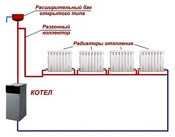 This CO distribution is not intended for multi-storey buildings and single-storey houses with a large area.
Advice: Regardless of the presence and height of the accelerating manifold, for good circulation of the coolant, it is recommended to create a slope of the main pipeline of 5°; on the supply branch to the radiators; on the return side - towards the boiler unit.
With mechanical circulation of water, there is no need for an accelerating manifold; its function is performed by a circulation pump. It is mounted on the return circuit, directly next to the boiler plant.
The figure shows a version of a single-pipe CO with horizontal distribution and forced circulation. This scheme is successfully used for one-story buildings, with the number of radiators 5-7 pcs.
 Vertical single-pipe CO with overhead wiring, designed for buildings with several floors, is quite popular. May have the following implementations:

To answer the question of which heating system is more effective: one-pipe or two-pipe, it is necessary to study them in detail.
Two-pipe version
The main design feature of heating a private house with this method of execution is that each of the radiators is connected to a different pipeline: supply and return. This is what, according to many “professionals,” significantly increases the cost of the heating system. In fact, this design allows you to save on the number of shaped products and on the diameter of the main pipelines.
There are several schemes for implementing two-pipe heating:
- Horizontal.
- Vertical, with top wiring.
- Vertical, with bottom coolant supply.
In turn, the horizontal two-pipe design can have three implementations:
A. Dead-end or oncoming.
V. Poputnaya.
C. With radial distribution or collector.
 Figure A shows the difference between a one-pipe heating system and a two-pipe one, despite the similar horizontal implementation.
Structurally, the simplest horizontal two-pipe circuit looks like this: A coolant supply pipe departs from the heat generator, which goes into each radiator. The cooled coolant from the batteries is removed through the second pipe - the return pipe, which returns it to the boiler unit.
Water circulation is ensured by a circulation pump; the expansion tank compensates for the expansion of the coolant when it is heated; the safety valve provides protection against high pressure in the circuit; shut-off valves on radiators serve to dismantle the latter; an air vent is required at the top point of the circuit to prevent airing of the system.

Horizontal types of CO are relevant for one-story buildings. Each of them has its own advantages and disadvantages:
- Dead-end wiring has a small consumption of expensive pipe. The disadvantage is the large length of the contour.
- Along the way, adjusting the operation of the CO is easily realized. The disadvantage is the high consumption of material.
- In the manifold wiring, each heating device is connected to the boiler with its own pair of pipes, supply and return, which makes it easy to adjust the heating of a specific radiator. The disadvantage is the high consumption of pipes and their rather complicated installation.
Vertical two-pipe CO systems with lower and upper wiring have shown themselves to be excellent in two- to three-story private houses. With top distribution, the coolant rises through the supply pipeline to the highest point of the circuit, after which it is distributed along the return risers, passes through all radiators and returns to the boiler installation. The main advantage of the upper wiring is the creation of higher pressure in the circuit.
With vertical bottom wiring, the coolant is supplied from a line located under the floor of the lower floor or in the basement of the house. Next, the coolant moves along vertical risers and radiators installed on them. Rising to the highest point, the cooled water in the batteries flows through the return riser into the boiler unit. The advantage of this approach is the higher temperature of the coolant entering the radiators. The disadvantage is the possible airing of the circuit. 
Choosing the best scheme for a private house
Now that we have a general idea about the types of heating and circuit connection options, it remains to decide what to choose, a single-pipe or two-pipe heating system?
There is an opinion that the former are more economical, easier to install and repair, and require fewer materials for sale. In fact, these advantages are quite controversial. For example, when such a CO operates, the end batteries on the branch receive coolant that has already cooled down in the previous ones. To maintain the required air temperature in the rooms located at the end of the circuit, it is necessary to increase the number of sections, and this is an additional cost. And all this against the background of the complete impossibility of automation, which will be responsible for maintaining the temperature balance necessary for comfortable living.
In a two-pipe system, the temperature of the coolant supplied to the batteries is the same, so there is no need to increase the number of sections of distant radiators in the circuit. The separation of the supply and return branches makes it possible to automate through the use of thermostatic valves.
Important! In fact, both one-pipe and two-pipe wiring have a right to exist. It should be understood that the choice is up to the developer, but only an experienced specialist will help you make the right choice of heating system for a private home.
This guide is intended for owners of small private houses who want to independently organize home heating in order to save money. The most rational solution for such buildings is a closed heating system (abbreviated as ZSO), operating with excess coolant pressure. Let's consider its operating principle, types of wiring diagrams and do-it-yourself device.
Operating principle of closed CO
A closed (otherwise known as closed) heating system is a network of pipelines and heating devices in which the coolant is completely isolated from the atmosphere and moves forcibly - from a circulation pump. Any SSO necessarily includes the following elements:
- heating unit - gas, solid fuel or electric boiler;
- safety group consisting of a pressure gauge, safety and air valve;
- heating devices - radiators or underfloor heating circuits;
- connecting pipelines;
- a pump that pumps water or non-freezing liquid through pipes and batteries;
- coarse mesh filter (dirt collector);
- closed expansion tank equipped with a membrane (rubber “bulb”);
- shut-off valves, balancing valves.
Note. Depending on the design, the ZSO additionally includes modern devices for regulating temperature and coolant flow - radiator thermal heads, check and three-way valves, thermostats, and the like.
The operating algorithm of a closed type system with forced circulation looks like this:
- After assembly and pressure testing, the pipeline network is filled with water until the pressure gauge shows a minimum pressure of 1 bar.
- The automatic air vent of the safety group releases air from the system during the filling process. He also removes gases that accumulate in pipes during operation.
- The next step is to turn on the pump, start the boiler and warm up the coolant.
- As a result of heating, the pressure inside the ZSO increases to 1.5-2 Bar.
- The increase in the volume of hot water is compensated by a membrane expansion tank.
- If the pressure rises above the critical point (usually 3 Bar), the safety valve will release excess liquid.
- Once every 1-2 years, the system must undergo an emptying and flushing procedure.
The principle of operation of an apartment building's SSS is absolutely identical - the movement of coolant through pipes and radiators is ensured by network pumps located in an industrial boiler room. There are also expansion tanks there; the temperature is regulated by a mixing or elevator unit.
How a closed heating system functions is explained in the video:
Positive qualities and disadvantages
The main differences between closed heat supply networks and outdated open systems with natural circulation are the lack of contact with the atmosphere and the use of transfer pumps. This gives rise to a number of advantages:
- the required pipe diameters are reduced by 2-3 times;
- the slopes of the highways are kept to a minimum, since they serve to drain water for the purpose of flushing or repairs;
- the coolant is not lost by evaporation from an open tank, therefore, you can safely fill pipelines and batteries with antifreeze;
- ZSO is more economical in terms of heating efficiency and cost of materials;
- closed heating is better regulated and automated and can operate in conjunction with solar collectors;
- the forced flow of coolant makes it possible to organize floor heating with pipes embedded inside the screed or in the grooves of the walls.

A gravitational (gravity-flowing) open system outperforms the ZSO in terms of energy independence - the latter is unable to operate normally without a circulation pump. Point two: a closed network contains much less water and if, for example, a TT boiler overheats, there is a high probability of boiling and the formation of a vapor lock.
Reference. A wood-burning boiler is saved from boiling by a buffer tank that absorbs excess heat.
Types of closed systems
Before you buy heating equipment, pipeline fittings and materials, you need to choose the preferred option for a closed water system. Master plumbers practice installation of four main circuits:
- Single-pipe with vertical and horizontal wiring (Leningrad).
- Collector, otherwise – radial.
- Double-pipe dead-end with arms of the same or different lengths.
- The Tichelman loop is a circular route with associated water movement.
Additional Information. Closed heating systems also include water heated floors. It is much more difficult to assemble radiator heating; it is not recommended for beginners to undertake such installation.

We propose to consider each scheme separately, analyzing the pros and cons. As an example, let’s take the project of a one-story private house with an area of 100 m² with an attached boiler room, the layout of which is shown in the drawing. The amount of heat load for heating has already been calculated, the required amount of heat is indicated for each room.
Installation of wiring elements and connection to a heat source is performed in approximately the same way. The installation of a circulation pump is usually provided in the return line; a sump tank, a make-up pipe with a tap and (if viewed downstream) are mounted in front of it. Typical wiring for a solid fuel and gas boiler is shown in the diagrams.
 The expansion tank is not shown in the figure.
Read more about installation and methods of connecting heating units using various energy sources in separate manuals:
Single-pipe wiring
The popular horizontal “Leningradka” scheme is one ring main of increased diameter, into which all heating devices are connected. Passing through the pipe, the flow of heated coolant is divided at each tee and flows into the battery, as shown in the sketch below.
 Having reached the branch, the flow is divided into 2 parts, about a third flows into the radiator, where it cools and returns to the main line again
 Having transferred heat to the room, the cooled water returns back to the main line, mixes with the main flow and moves to the next radiator. Accordingly, the second heating device receives water cooled by 1-3 degrees and again takes the required amount of heat from it.
 Leningrad horizontal wiring - one ring line bypasses all heating devices
 Result: increasingly cold water flows into each subsequent radiator. This imposes certain restrictions on a closed one-pipe system:
- The heat transfer of the third, fourth and subsequent batteries must be calculated with a margin of 10-30%, adding additional sections.
- The minimum diameter of the line is DN20 (internal). The outer size of PPR pipes will be 32 mm, metal-plastic and cross-linked polyethylene – 26 mm.
- The cross-section of the supply pipes to the heaters is DN10, the outer diameter is 20 and 16 mm for PPR and PEX, respectively.
- The maximum number of heating devices in one Leningradka ring is 6 pieces. If you take more, problems will arise with increasing the number of sections of the last radiators and increasing the diameter of the distribution pipe.
- The cross-section of the ring pipeline does not decrease throughout its entire length.
Reference. Single-pipe distribution can be vertical - with lower or upper distribution of coolant through risers. Such systems are used to organize gravity flow in two-story private cottages or operate under pressure in old apartment buildings.
A single-pipe closed-type heating system will be inexpensive if it is soldered from polypropylene. In other cases, it will significantly hit your pocket due to the price of the main pipe and large fittings (tees). What the “Leningradka” looks like in our one-story house is demonstrated in the drawing. 
Since the total number of heating devices exceeds 6, the system is divided into 2 rings with a common return manifold. The inconvenience of installing single-pipe wiring is noticeable - you have to cross doorways. A decrease in flow in one radiator causes a change in water flow in the remaining batteries, so balancing the “Leningrad” consists of coordinating the operation of all heaters.
Advantages of the beam scheme
Why the collector system received such a name can be clearly seen in the diagram presented. From the comb installed in the center of the building, individual coolant supply lines diverge to each heating device. The lines are laid in the form of rays along the shortest path - under the floors.
The collector of the closed beam system is fed directly from the boiler; circulation in all circuits is provided by a single pump located in the combustion chamber. In order to protect the branches from airing during the filling process, automatic valves - air vents - are installed on the comb.

Strengths of the collector system:
- the circuit is energy efficient because it allows you to accurately dose the amount of coolant sent to each radiator;
- the heating network is easy to fit into any interior - supply pipes can be hidden in the floor, walls or behind a suspended (suspended) ceiling;
- hydraulic balancing of the branches is carried out using manual valves and flow meters (rotameters) installed on the manifold;
- water is supplied to all batteries at the same temperature;
- the operation of the circuit is easy to automate - the manifold control valves are equipped with servo drives that close the flow according to a signal from the thermostats;
- ZSO of this type is suitable for cottages of any size and number of storeys - a separate collector is installed at each level of the building, distributing heat to groups of radiators.
From a financial investment point of view, a closed beam system is not very expensive. A lot of pipes are consumed, but their diameter is minimal - 16 x 2 mm (DN10). Instead of a factory comb, it is quite acceptable to use one soldered from polypropylene tees or twisted from steel fittings. True, without rotameters, adjustment of the heating network will have to be done using radiator balancing valves.
 The distribution comb is placed in the center of the building, the radiator lines are laid directly
 There are few disadvantages of beam wiring, but they are worth attention:
- Hidden installation and testing of pipelines is carried out only at the stage of new construction or major repairs. It is unrealistic to install radiator lines in the floors of a lived-in house or apartment.
- It is highly desirable to locate the collector in the center of the building, as shown in the drawing of a one-story house. The goal is to make the connections to the batteries approximately the same length.
- In the event of a leak in a pipe embedded in a floor screed, it is quite difficult to find the location of the defect without a thermal imager. Do not make connections in the screed, otherwise you risk encountering the problem shown in the photo.
 Leaking connection inside a concrete monolith
 Two-pipe options
When installing autonomous heating of apartments and country houses, 2 types of such schemes are used:
- Dead-end (another name is shoulder). The heated water is distributed to the heating devices through one line, and is collected and flows back to the boiler through the second line.
- The Tichelman loop (passing distribution) is a circular two-pipe network where the heated and cooled coolant moves in one direction. The principle of operation is similar - the batteries receive hot water from one line, and the cooled water is discharged into the second pipeline - the return line.
Note. In a closed associated system, the return line starts from the first radiator, and the supply line ends at the last one. The diagram below will help you figure it out.

What is good about a dead-end closed heating system for a private house:
- the number of “arms” - dead-end branches - is limited only by the power of the boiler installation, so two-pipe wiring is suitable for any building;
- pipes are laid open or closed inside building structures - at the request of the homeowner;
- as in the radial circuit, equally hot water comes to all batteries;
- ZSO lends itself well to regulation, automation and balancing;
- correctly positioned “shoulders” do not cross doorways;
- In terms of the cost of materials and installation, a dead-end wiring will be cheaper than a single-pipe one if the assembly is carried out using metal-plastic or polyethylene pipes.
 The optimal option for connecting batteries is two separate branches that go around the premises on both sides
 Designing a closed shoulder system for a country house or residential building with an area of up to 200 square meters is not particularly difficult. Even if you make branches of different lengths, the circuit can be balanced through deep balancing. An example of wiring in a one-story building of 100 m² with two “shoulders” is shown above in the drawing.
Advice. When choosing the length of the branches, the heating load should be taken into account. The optimal number of batteries on each “arm” is from 4 to 6 pcs.
 Connecting heaters with associated coolant movement
 The Tichelman loop is an alternative version of a closed two-pipe network, which involves combining a large number of heating devices (over 6 pieces) into a single ring. Take a look at the associated wiring diagram and note: no matter what radiator the coolant flows through, the total length of the route will not change.
This results in almost ideal hydraulic equilibrium of the system - the resistance of all sections of the network is the same. This significant advantage of the Tichelman loop over other closed wiring also entails the main disadvantage - 2 lines will inevitably cross the doorway. Bypass options are under the floors and above the door frame with the installation of automatic air vents.
 Disadvantage - the ring loop passes through the entrance door opening
 Choosing a heating scheme for a country house
- Dead-end two-pipe.
- Collector.
- Two-pipe associated.
- Single-pipe.
Hence the advice: you can’t go wrong if you choose the first option for a house with an area of up to 200 m² - a dead-end scheme; it will work in any case. Beam wiring is inferior to it in two respects - price and the possibility of installation in rooms with finished finishing.
A single-pipe version of the heating network is perfect for a small house with a square footage of each floor of up to 70 m². The Tichelman loop is appropriate for long branches that do not cross the door, for example, heating the upper floors of a building. How to choose the right system for houses of various shapes and number of storeys, watch the video:
Regarding the selection of pipe diameters and installation, we will give several recommendations:
- If the area of the home does not exceed 200 m², it is not necessary to carry out calculations - use the advice of the expert in the video or take the cross-section of the pipelines according to the diagrams given above.
- When you need to “hang” more than six radiators on a branch of a dead-end wiring, increase the diameter of the pipe by 1 standard size - instead of DN15 (20 x 2 mm), take DN20 (25 x 2.5 mm) and lay it to the fifth battery. Next, run lines with a smaller cross-section specified initially (DN15).
- In a building under construction, it is better to do radial wiring and select radiators with bottom connections. Be sure to insulate underground lines and protect them with plastic corrugation at the intersections of walls.
- If you don’t know how to properly solder polypropylene, then it’s better not to mess with PPR pipes. Install heating made of cross-linked polyethylene or metal-plastic on compression or press fittings.
- Do not embed pipeline joints in walls or screed, so as not to have problems with leaks in the future.

