Thanks to the miniature size of LEDs, engineers have learned to create lamps of a wide variety of designs, including repeating the shape of fluorescent and halogen lamps. Tubular fluorescent lamps of the T8 type with a G13 socket were no exception. They can be easily replaced with a similar-shaped tube with LEDs, significantly improving the optical-energy characteristics of the existing lamp.
Is it necessary to change fluorescent light bulbs to LED lamps?
Today we can confidently say that LED light bulbs of any form factor are superior to their fluorescent counterparts in almost all respects. Moreover, LED technologies continue to progress, which means that products based on them will be even more advanced in the future. To confirm the above, a comparative description of two types of tubular lamps is given below.
T8 fluorescent lamps:
- MTBF is about 2000 hours and depends on the number of starts, but not more than 2000 cycles;
- light spreads in all directions, which is why they need a reflector;
- gradual increase in brightness at the moment of switching on;
- the ballast (ballast) serves as a source of network interference;
- degradation of the protective layer with a decrease in luminous flux by 30%;
- The glass flask and the mercury vapor inside it require careful handling and disposal.
T8 LED lamps:
In addition, T8 LED lamps have twice the light output with equal energy consumption, are less likely to fail and have a manufacturer’s warranty. The ability to place different numbers of LEDs inside the bulb allows you to achieve an optimal level of illumination. This means that instead of a T8-G13-600 mm 18 W fluorescent lamp, you can install a 9, 18 or 24 W LED lamp of the same length.
The abbreviation T8 indicates the diameter of the glass tube (8/8 inch or 2.54 cm), and G13 is the type of cap indicating the pin spacing in mm.
Having weighed all the pros and cons, we can conclude that converting a fluorescent lamp to an LED light bulb is completely justified, both from a technical and economic point of view.
Connection diagrams
Before moving on to upgrading the lamp by replacing T8 fluorescent lamps with LED lamps, you first need to properly understand the circuits. All fluorescent lamps are connected in one of two ways:
In raster ceiling lamps, 4 fluorescent tubes are connected to 2 electronic ballasts, each of which provides operation of two lamps, or to a combined ballast, including 4 starters, 2 chokes and 1 capacitor.
The connection diagram for the T8 LED lamp does not contain any additional elements (Fig. 3).  A stabilized power supply (driver) for LEDs is already built inside the case. Along with it, under a glass or plastic diffuser, there is a printed circuit board with LEDs, mounted on an aluminum radiator. The 220V supply voltage can be supplied to the driver through the pins of the base, either on one side (usually on Ukrainian-made products) or on both sides. In the first case, the pins located on the other side serve as fasteners. In the second case, 1 or 2 pins can be used on each side. Therefore, before modifying the lamp, you need to carefully study the connection diagram shown on the LED lamp body or in its documentation. The most common are T8 LED lamps with phase and neutral connections from different sides, so alteration of the lamp will be considered based on this option.
What needs to be changed?
By carefully looking at the diagrams, even an inexperienced electrician will understand how to connect an LED lamp instead of a fluorescent one. In a luminaire with ballasts, you need to perform the following steps:
- Turn off the circuit breaker and make sure there is no voltage.
- Remove the protective cover, gaining access to the circuit elements.
- Remove the capacitor, inductor, and starter from the electrical circuit.
- Separate the wires going to the cartridge terminals and connect them directly to the phase and neutral wires.
- The remaining wires can be removed or insulated.
- Insert a T8 G13 lamp with LEDs and perform a test run.
The contacts in the form of pins for connecting the T8 LED lamp are marked on its base with the symbols “L” and “N”.
Converting a fluorescent lamp with electronic ballast is even easier. To do this, just unsolder or cut with wire cutters the wires going to and from the ballast. Then connect the phase and neutral wires to the wires of the left and right sockets of the lamp. Insulate the connection point, insert an LED lamp and apply supply voltage.
It is much easier to install and connect a T8 LED lamp in Philips branded lamps. The Dutch company has made the task as simple as possible for its consumers. To install an LED lamp with a length of 600 mm, 900 mm, 1200 mm or 1500 mm, you will need to unscrew the starter and screw in the plug supplied in the kit in its place. In this case, there is no need to disassemble the lamp body and remove the choke.
When choosing a T8 G13 LED lamp, you should pay attention to the design of the base. It can be rotary or have a rigid connection to the body. Models with a rotating base are considered to be the most universal. They can be screwed into any converted light fixture, with either vertical or horizontal slots in the socket. And by adjusting the angle of the lamp, you can change the direction of the light flux.
It is not uncommon to find negative reviews on the Internet that the service life of T8 LED lamps is much less than stated. As a rule, such comments are left by people who bought a Chinese “no name” for the price of a fluorescent lamp. Naturally, the quality of the LEDs and drivers will not allow it to work even for one year.
Read also
Due to low energy consumption, theoretical durability and lower prices, incandescent and energy-saving lamps are rapidly replacing them. But, despite the declared service life of up to 25 years, they often burn out without even serving the warranty period.
Unlike incandescent lamps, 90% of burnt-out LED lamps can be successfully repaired with your own hands, even without special training. The examples presented will help you repair failed LED lamps.
Before you start repairing an LED lamp, you need to understand its structure. Regardless of the appearance and type of LEDs used, all LED lamps, including filament bulbs, are designed the same. If you remove the walls of the lamp body, you can see the driver inside, which is a printed circuit board with radio elements installed on it.

Any LED lamp is designed and works as follows. The supply voltage from the contacts of the electric cartridge is supplied to the terminals of the base. Two wires are soldered to it, through which voltage is supplied to the driver input. From the driver, the DC supply voltage is supplied to the board on which the LEDs are soldered.
The driver is an electronic unit - a current generator that converts the supply voltage into the current required to light the LEDs.
Sometimes, to diffuse light or protect against human contact with unprotected conductors of a board with LEDs, it is covered with diffusing protective glass.
About filament lamps
In appearance, a filament lamp is similar to an incandescent lamp. The design of filament lamps differs from LED lamps in that they do not use a board with LEDs as light emitters, but a sealed glass flask filled with gas, in which one or more filament rods are placed. The driver is located in the base.

The filament rod is a glass or sapphire tube with a diameter of about 2 mm and a length of about 30 mm, on which 28 miniature LEDs coated in series with a phosphor are attached and connected. One filament consumes about 1 W of power. My operating experience shows that filament lamps are much more reliable than those made on the basis of SMD LEDs. I believe that over time they will replace all other artificial light sources.
Examples of LED lamp repairs
Attention, the electrical circuits of the LED lamp drivers are galvanically connected to the phase of the electrical network and therefore extreme care should be taken. Touching an unprotected part of a person’s body to exposed parts of a circuit connected to an electrical network can cause serious damage to health, including cardiac arrest.
LED lamp repair
ASD LED-A60, 11 W on SM2082 chip
Currently, powerful LED light bulbs have appeared, the drivers of which are assembled on SM2082 type chips. One of them worked for less than a year and ended up being repaired. The light went out randomly and came on again. When you tapped it, it responded with light or extinguishing. It became obvious that the problem was poor contact.

To get to the electronic part of the lamp, you need to use a knife to pick up the diffuser glass at the point of contact with the body. Sometimes it is difficult to separate the glass, since when it is seated, silicone is applied to the fixing ring.

After removing the light-scattering glass, access to the LEDs and the SM2082 current generator microcircuit became available. In this lamp, one part of the driver was mounted on an aluminum LED printed circuit board, and the second on a separate one.

An external inspection did not reveal any defective soldering or broken tracks. I had to remove the board with LEDs. To do this, the silicone was first cut off and the board was pryed off by the edge with a screwdriver blade.
To get to the driver located in the lamp body, I had to unsolder it by heating two contacts with a soldering iron at the same time and moving it to the right.

On one side of the driver circuit board, only an electrolytic capacitor with a capacity of 6.8 μF for a voltage of 400 V was installed.

On the reverse side of the driver board, a diode bridge and two series-connected resistors with a nominal value of 510 kOhm were installed.

In order to figure out which of the boards the contact was missing, we had to connect them, observing the polarity, using two wires. After tapping the boards with the handle of a screwdriver, it became obvious that the fault lies in the board with the capacitor or in the contacts of the wires coming from the base of the LED lamp.

Since the soldering did not raise any suspicions, I first checked the reliability of the contact in the central terminal of the base. It can be easily removed if you pry it over the edge with a knife blade. But the contact was reliable. Just in case, I tinned the wire with solder.
It is difficult to remove the screw part of the base, so I decided to use a soldering iron to solder the soldering wires coming from the base. When I touched one of the soldering joints, the wire became exposed. A “cold” solder was discovered. Since there was no way to get to the wire to strip it, I had to lubricate it with FIM active flux and then solder it again.

After assembly, the LED lamp consistently emitted light, despite hitting it with the handle of a screwdriver. Checking the light flux for pulsations showed that they are significant with a frequency of 100 Hz. Such an LED lamp can only be installed in luminaires for general lighting.
Driver circuit diagram
LED lamp ASD LED-A60 on SM2082 chip
The electrical circuit of the ASD LED-A60 lamp, thanks to the use of a specialized SM2082 microcircuit in the driver to stabilize the current, turned out to be quite simple.

The driver circuit works as follows. The AC supply voltage is supplied through fuse F to the rectifier diode bridge assembled on the MB6S microassembly. Electrolytic capacitor C1 smoothes out ripples, and R1 serves to discharge it when the power is turned off.
From the positive terminal of the capacitor, the supply voltage is supplied directly to the LEDs connected in series. From the output of the last LED, the voltage is supplied to the input (pin 1) of the SM2082 microcircuit, the current in the microcircuit is stabilized and then from its output (pin 2) goes to the negative terminal of capacitor C1.
Resistor R2 sets the amount of current flowing through the HL LEDs. The amount of current is inversely proportional to its rating. If the value of the resistor is decreased, the current will increase; if the value is increased, the current will decrease. The SM2082 microcircuit allows you to adjust the current value with a resistor from 5 to 60 mA.
LED lamp repair
ASD LED-A60, 11 W, 220 V, E27
The repair included another ASD LED-A60 LED lamp, similar in appearance and with the same technical characteristics as the one repaired above.

When turned on, the lamp came on for a moment and then did not shine. This behavior of LED lamps is usually associated with a driver failure. So I immediately started disassembling the lamp.
The light-scattering glass was removed with great difficulty, since along the entire line of contact with the body it was, despite the presence of a retainer, generously lubricated with silicone. To separate the glass, I had to look for a pliable place along the entire line of contact with the body using a knife, but still there was a crack in the body.

To gain access to the lamp driver, the next step was to remove the LED printed circuit board, which was pressed along the contour into the aluminum insert. Despite the fact that the board was aluminum and could be removed without fear of cracks, all attempts were unsuccessful. The board held tight.
It was also not possible to remove the board together with the aluminum insert, since it fit tightly to the case and was seated with the outer surface on silicone.

I decided to try removing the driver board from the base side. To do this, first, a knife was pryed out of the base and the central contact was removed. To remove the threaded part of the base, it was necessary to slightly bend its upper flange so that the core points would disengage from the base.
The driver became accessible and was freely extended to a certain position, but it was not possible to remove it completely, although the conductors from the LED board were sealed off.

The LED board had a hole in the center. I decided to try to remove the driver board by hitting its end through a metal rod threaded through this hole. The board moved a few centimeters and hit something. After further blows, the lamp body cracked along the ring and the board with the base of the base separated.
As it turned out, the board had an extension whose shoulders rested against the lamp body. It looks like the board was shaped this way to limit movement, although it would have been enough to fix it with a drop of silicone. Then the driver would be removed from either side of the lamp.

The 220 V voltage from the lamp base is supplied through a resistor - fuse FU to the MB6F rectifier bridge and is then smoothed out by an electrolytic capacitor. Next, the voltage is supplied to the SIC9553 chip, which stabilizes the current. Parallel connected resistors R20 and R80 between pins 1 and 8 MS set the amount of LED supply current.

The photo shows a typical electrical circuit diagram provided by the manufacturer of the SIC9553 chip in the Chinese datasheet.

This photo shows the appearance of the LED lamp driver from the installation side of the output elements. Since space allowed, to reduce the pulsation coefficient of the light flux, the capacitor at the driver output was soldered to 6.8 μF instead of 4.7 μF.

If you have to remove the drivers from the body of this lamp model and cannot remove the LED board, you can use a jigsaw to cut the lamp body around the circumference just above the screw part of the base.

In the end, all my efforts to extract the driver turned out to be useful only in understanding the structure of the LED lamp. The driver turned out to be OK.
The flash of the LEDs at the moment of switching on was caused by a breakdown in the crystal of one of them as a result of a voltage surge when the driver was started, which misled me. It was necessary to ring the LEDs first.
An attempt to test the LEDs with a multimeter was unsuccessful. The LEDs did not light up. It turned out that two light-emitting crystals connected in series are installed in one case, and in order for the LED to start flowing current, it is necessary to apply a voltage of 8 V to it.
A multimeter or tester turned on in resistance measurement mode produces a voltage within 3-4 V. I had to check the LEDs using a power supply, supplying 12 V to each LED through a 1 kOhm current-limiting resistor.
There was no replacement LED available, so the pads were shorted with a drop of solder instead. This is safe for driver operation, and the power of the LED lamp will decrease by only 0.7 W, which is almost imperceptible.

After repairing the electrical part of the LED lamp, the cracked body was glued with quick-drying Moment super glue, the seams were smoothed by melting the plastic with a soldering iron and leveled with sandpaper.

Just for fun, I did some measurements and calculations. The current flowing through the LEDs was 58 mA, the voltage was 8 V. Therefore, the power supplied to one LED was 0.46 W. With 16 LEDs, the result is 7.36 W, instead of the declared 11 W. Perhaps the manufacturer has indicated the total power consumption of the lamp, taking into account losses in the driver.
The service life of the ASD LED-A60, 11 W, 220 V, E27 LED lamp declared by the manufacturer raises serious doubts in my mind. In the small volume of the plastic lamp body, with low thermal conductivity, significant power is released - 11 W. As a result, the LEDs and driver operate at the maximum permissible temperature, which leads to accelerated degradation of their crystals and, as a consequence, to a sharp reduction in their time between failures.
LED lamp repair
LED smd B35 827 ERA, 7 W on BP2831A chip
An acquaintance shared with me that he bought five light bulbs like in the photo below, and after a month they all stopped working. He managed to throw away three of them, and, at my request, brought two for repairs.

The light bulb worked, but instead of bright light it emitted a flickering weak light with a frequency of several times per second. I immediately assumed that the electrolytic capacitor had swollen; usually, if it fails, the lamp begins to emit light like a strobe.

The light-scattering glass came off easily, it was not glued. It was fixed by a slot on its rim and a protrusion in the lamp body.

The driver was secured using two solders to a printed circuit board with LEDs, as in one of the lamps described above.

A typical driver circuit on the BP2831A chip taken from the datasheet is shown in the photograph. The driver board was removed and all simple radio elements were checked; they all turned out to be in good order. I had to start checking the LEDs.

The LEDs in the lamp were installed of an unknown type with two crystals in the housing and inspection did not reveal any defects. By connecting the leads of each LED in series, I quickly identified the faulty one and replaced it with a drop of solder, as in the photo.
The light bulb worked for a week and was repaired again. Shorted the next LED. A week later I had to short-circuit another LED, and after the fourth I threw out the light bulb because I was tired of repairing it.
The reason for the failure of light bulbs of this design is obvious. LEDs overheat due to insufficient heat sink surface, and their service life is reduced to hundreds of hours.
Why is it permissible to short-circuit the terminals of burnt-out LEDs in LED lamps?
The LED lamp driver, unlike a constant voltage power supply, produces a stabilized current value at the output, not a voltage. Therefore, regardless of the load resistance within the specified limits, the current will always be constant and, therefore, the voltage drop across each of the LEDs will remain the same.
Therefore, as the number of series-connected LEDs in the circuit decreases, the voltage at the driver output will also decrease proportionally.
For example, if 50 LEDs are connected in series to the driver, and each of them drops a voltage of 3 V, then the voltage at the driver output is 150 V, and if you short-circuit 5 of them, the voltage will drop to 135 V, and the current will not change.

But the efficiency of the driver assembled according to this scheme will be low and the power loss will be more than 50%. For example, for an LED light bulb MR-16-2835-F27 you will need a 6.1 kOhm resistor with a power of 4 watts. It turns out that the resistor driver will consume power that exceeds the power consumption of LEDs and placing it in a small LED lamp housing, due to the release of more heat, will be unacceptable.
But if there is no other way to repair an LED lamp and it is very necessary, then the resistor driver can be placed in a separate housing; anyway, the power consumption of such an LED lamp will be four times less than incandescent lamps. It should be noted that the more LEDs connected in series in a light bulb, the higher the efficiency will be. With 80 series-connected SMD3528 LEDs, you will need an 800 Ohm resistor with a power of only 0.5 W. The capacitance of capacitor C1 will need to be increased to 4.7 µF.
Finding faulty LEDs
After removing the protective glass, it becomes possible to check the LEDs without peeling off the printed circuit board. First of all, a careful inspection of each LED is carried out. If even the smallest black dot is detected, not to mention blackening of the entire surface of the LED, then it is definitely faulty.
When inspecting the appearance of the LEDs, you need to carefully examine the quality of the soldering of their terminals. One of the light bulbs being repaired turned out to have four LEDs that were poorly soldered.

The photo shows a light bulb that had very small black dots on its four LEDs. I immediately marked the faulty LEDs with crosses so that they were clearly visible.
Faulty LEDs may not have any changes in appearance. Therefore, it is necessary to check each LED with a multimeter or pointer tester turned on in resistance measurement mode.
There are LED lamps in which standard LEDs are installed in appearance, in the housing of which two crystals connected in series are mounted at once. For example, lamps of the ASD LED-A60 series. To test such LEDs, it is necessary to apply a voltage of more than 6 V to its terminals, and any multimeter produces no more than 4 V. Therefore, checking such LEDs can only be done by applying a voltage of more than 6 (recommended 9-12) V to them from the power source through a 1 kOhm resistor .

The LED is checked like a regular diode; in one direction the resistance should be equal to tens of megaohms, and if you swap the probes (this changes the polarity of the voltage supply to the LED), then it should be small, and the LED may glow dimly.

When checking and replacing LEDs, the lamp must be fixed. To do this, you can use a suitable sized round jar.
You can check the serviceability of the LED without an additional DC source. But this verification method is possible if the light bulb driver is working properly. To do this, it is necessary to apply supply voltage to the base of the LED light bulb and short-circuit the terminals of each LED in series with each other using a wire jumper or, for example, the jaws of metal tweezers.

If suddenly all the LEDs light up, it means that the shorted one is definitely faulty. This method is suitable if only one LED in the circuit is faulty. With this method of checking, it is necessary to take into account that if the driver does not provide galvanic isolation from the electrical network, as for example in the diagrams above, then touching the LED solders with your hand is unsafe.
If one or even several LEDs turn out to be faulty and there is nothing to replace them with, then you can simply short-circuit the contact pads to which the LEDs were soldered. The light bulb will work with the same success, only the luminous flux will decrease slightly.
Other malfunctions of LED lamps
If checking the LEDs showed their serviceability, then the reason for the light bulb’s inoperability lies in the driver or in the soldering areas of the current-carrying conductors.

For example, in this light bulb a cold solder connection was found on the conductor supplying power to the printed circuit board. The soot released due to poor soldering even settled on the conductive paths of the printed circuit board. The soot was easily removed by wiping with a rag soaked in alcohol. The wire was soldered, stripped, tinned and re-soldered into the board. I was lucky with the repair of this light bulb.
Of the ten failed bulbs, only one had a faulty driver and a broken diode bridge. The driver repair consisted of replacing the diode bridge with four IN4007 diodes, designed for a reverse voltage of 1000 V and a current of 1 A.
Soldering SMD LEDs
To replace a faulty LED, it must be desoldered without damaging the printed conductors. The LED from the donor board also needs to be desoldered for replacement without damage.
It is almost impossible to desolder SMD LEDs with a simple soldering iron without damaging their housing. But if you use a special tip for a soldering iron or put an attachment made of copper wire on a standard tip, then the problem can be easily solved.

LEDs have polarity and when replacing, you need to install it correctly on the printed circuit board. Typically, printed conductors follow the shape of the leads on the LED. Therefore, a mistake can only be made if you are inattentive. To seal an LED, it is enough to install it on a printed circuit board and heat its ends with the contact pads with a 10-15 W soldering iron.
If the LED burns out like carbon, and the printed circuit board underneath is charred, then before installing a new LED, you must clean this area of the printed circuit board from burning, since it is a current conductor. When cleaning, you may find that the LED solder pads are burnt or peeled off.

In this case, the LED can be installed by soldering it to adjacent LEDs if the printed traces lead to them. To do this, you can take a piece of thin wire, bend it in half or three times, depending on the distance between the LEDs, tin it and solder it to them.
Repair of LED lamp series "LL-CORN" (corn lamp)
E27 4.6W 36x5050SMD
The design of the lamp, which is popularly called a corn lamp, shown in the photo below differs from the lamp described above, therefore the repair technology is different.

The design of LED SMD lamps of this type is very convenient for repair, since there is access to test the LEDs and replace them without disassembling the lamp body. True, I still disassembled the light bulb for fun in order to study its structure.

Checking the LEDs of an LED corn lamp is no different from the technology described above, but we must take into account that the SMD5050 LED housing contains three LEDs at once, usually connected in parallel (three dark points of the crystals are visible on the yellow circle), and during testing all three should glow.

A faulty LED can be replaced with a new one or short-circuited with a jumper. This will not affect the reliability of the lamp, only the luminous flux will decrease slightly, unnoticeably to the eye.
The driver of this lamp is assembled according to the simplest circuit, without an isolating transformer, so touching the LED terminals when the lamp is on is unacceptable. Lamps of this design must not be installed in lamps that can be reached by children.
If all the LEDs are working, it means the driver is faulty, and the lamp will have to be disassembled to get to it.

To do this, you need to remove the rim from the side opposite the base. Using a small screwdriver or a knife blade, try in a circle to find the weak spot where the rim is glued the worst. If the rim gives way, then using the tool as a lever, the rim will easily come off around the entire perimeter.

The driver was assembled according to the electrical circuit, like the MR-16 lamp, only C1 had a capacity of 1 µF, and C2 - 4.7 µF. Due to the fact that the wires going from the driver to the lamp base were long, the driver was easily removed from the lamp body. After studying its circuit diagram, the driver was inserted back into the housing, and the bezel was glued into place with transparent Moment glue. The failed LED was replaced with a working one.
Repair of LED lamp "LL-CORN" (corn lamp)
E27 12W 80x5050SMD
When repairing a more powerful lamp, 12 W, there were no failed LEDs of the same design and in order to get to the drivers, we had to open the lamp using the technology described above.

This lamp gave me a surprise. The wires leading from the driver to the socket were short, and it was impossible to remove the driver from the lamp body for repair. I had to remove the base.

The lamp base was made of aluminum, cored around the circumference and held tightly. I had to drill out the mounting points with a 1.5 mm drill. After this, the base, pryed off with a knife, was easily removed.
But you can do without drilling the base if you use the edge of a knife to pry it around the circumference and slightly bend its upper edge. You should first put a mark on the base and body so that the base can be conveniently installed in place. To securely fasten the base after repairing the lamp, it will be enough to put it on the lamp body in such a way that the punched points on the base fall into the old places. Next, press these points with a sharp object.
Two wires were connected to the thread with a clamp, and the other two were pressed into the central contact of the base. I had to cut these wires.

As expected, there were two identical drivers, feeding 43 diodes each. They were covered with heat shrink tubing and taped together. In order for the driver to be placed back into the tube, I usually carefully cut it along the printed circuit board from the side where the parts are installed.

After repair, the driver is wrapped in a tube, which is fixed with a plastic tie or wrapped with several turns of thread.

In the electrical circuit of the driver of this lamp, protection elements are already installed, C1 for protection against pulse surges and R2, R3 for protection against current surges. When checking the elements, resistors R2 were immediately found to be open on both drivers. It appears that the LED lamp was supplied with a voltage that exceeded the permissible voltage. After replacing the resistors, I didn’t have a 10 ohm one at hand, so I set it to 5.1 ohms, and the lamp started working.
Repair of LED lamp series "LLB" LR-EW5N-5
The appearance of this type of light bulb inspires confidence. Aluminum body, high quality workmanship, beautiful design.

The design of the light bulb is such that disassembling it without the use of significant physical effort is impossible. Since the repair of any LED lamp begins with checking the serviceability of the LEDs, the first thing we had to do was remove the plastic protective glass.

The glass was fixed without glue on a groove made in the radiator with a collar inside it. To remove the glass, you need to use the end of a screwdriver, which will go between the fins of the radiator, to lean on the end of the radiator and, like a lever, lift the glass up.

Checking the LEDs with a tester showed that they are working properly, therefore, the driver is faulty and we need to get to it. The aluminum board was secured with four screws, which I unscrewed.

But contrary to expectations, behind the board there was a radiator plane, lubricated with heat-conducting paste. The board had to be returned to its place and the lamp continued to be disassembled from the base side.

Due to the fact that the plastic part to which the radiator was attached was held very tightly, I decided to go the proven route, remove the base and remove the driver through the opened hole for repair. I drilled out the core points, but the base was not removed. It turned out that it was still attached to the plastic due to the threaded connection.

I had to separate the plastic adapter from the radiator. It held up just like the protective glass. To do this, a cut was made with a hacksaw for metal at the junction of the plastic with the radiator and by turning a screwdriver with a wide blade, the parts were separated from each other.

After unsoldering the leads from the LED printed circuit board, the driver became available for repair. The driver circuit turned out to be more complex than previous light bulbs, with an isolation transformer and a microcircuit. One of the 400 V 4.7 µF electrolytic capacitors was swollen. I had to replace it.

A check of all semiconductor elements revealed a faulty Schottky diode D4 (pictured below on the left). There was an SS110 Schottky diode on the board, which was replaced with an existing analog 10 BQ100 (100 V, 1 A). The forward resistance of Schottky diodes is two times less than that of ordinary diodes. The LED light came on. The second light bulb had the same problem.
Repair of LED lamp series "LLB" LR-EW5N-3
This LED lamp is very similar in appearance to the "LLB" LR-EW5N-5, but its design is slightly different.

If you look closely, you can see that at the junction between the aluminum radiator and the spherical glass, unlike the LR-EW5N-5, there is a ring in which the glass is secured. To remove the protective glass, use a small screwdriver to pry it at the junction with the ring.

Three nine super-bright crystal LEDs are installed on an aluminum printed circuit board. The board is screwed to the heatsink with three screws. Checking the LEDs showed their serviceability. Therefore, the driver needs to be repaired. Having experience in repairing a similar LED lamp "LLB" LR-EW5N-5, I did not unscrew the screws, but unsoldered the current-carrying wires coming from the driver and continued disassembling the lamp from the base side.

The plastic connecting ring between the base and the radiator was removed with great difficulty. At the same time, part of it broke off. As it turned out, it was screwed to the radiator with three self-tapping screws. The driver was easily removed from the lamp body.

The screws that fasten the plastic ring of the base are covered by the driver and are difficult to see, but they are on the same axis with the thread to which the transition part of the radiator is screwed. Therefore, you can reach them with a thin Phillips screwdriver.

The driver turned out to be assembled using a transformer circuit. Checking all elements except the microcircuit did not reveal any failures. Consequently, the microcircuit is faulty; I couldn’t even find a mention of its type on the Internet. The LED light bulb could not be repaired; it will be useful for spare parts. But I studied its structure.
Repair of LED lamp series "LL" GU10-3W
At first glance, it turned out to be impossible to disassemble a burnt-out GU10-3W LED light bulb with protective glass. An attempt to remove the glass resulted in its chipping. When great force was applied, the glass cracked.

By the way, in the lamp marking, the letter G means that the lamp has a pin base, the letter U means that the lamp belongs to the class of energy-saving light bulbs, and the number 10 means the distance between the pins in millimeters.

LED light bulbs with a GU10 base have special pins and are installed in a socket with a rotation. Thanks to the expanding pins, the LED lamp is pinched in the socket and held securely even when shaking.

In order to disassemble this LED light bulb, I had to drill a hole with a diameter of 2.5 mm in its aluminum case at the level of the surface of the printed circuit board. The drilling location must be chosen in such a way that the drill does not damage the LED when exiting. If you don’t have a drill at hand, you can make a hole with a thick awl.

Next, a small screwdriver is inserted into the hole and, acting like a lever, the glass is lifted. I removed the glass from two light bulbs without any problems. If checking the LEDs with a tester shows their serviceability, then the printed circuit board is removed.

After separating the board from the lamp body, it immediately became obvious that the current-limiting resistors had burned out in both one and the other lamp. The calculator determined their nominal value from the stripes, 160 Ohms. Since the resistors burned out in LED bulbs of different batches, it is obvious that their power, judging by the size of 0.25 W, does not correspond to the power released when the driver operates at the maximum ambient temperature.

The driver circuit board was well filled with silicone, and I did not disconnect it from the board with the LEDs. I cut off the leads of the burnt resistors at the base and soldered them to more powerful resistors that were on hand. In one lamp I soldered a 150 Ohm resistor with a power of 1 W, in the second two in parallel with 320 Ohms with a power of 0.5 W.

In order to prevent accidental contact of the resistor terminal, to which the mains voltage is connected, with the metal body of the lamp, it was insulated with a drop of hot-melt adhesive. It is waterproof and an excellent insulator. I often use it for sealing, insulating and securing electrical wires and other parts.

Hot melt adhesive is available in the form of rods with a diameter of 7, 12, 15 and 24 mm in different colors, from transparent to black. It melts, depending on the brand, at a temperature of 80-150°, which allows it to be melted using an electric soldering iron. It is enough to cut a piece of the rod, place it in the right place and heat it. Hot-melt glue will acquire the consistency of May honey. After cooling it becomes hard again. When reheated it becomes liquid again.

After replacing the resistors, the functionality of both bulbs was restored. All that remains is to secure the printed circuit board and protective glass in the lamp body.

When repairing LED lamps, I used liquid nails “Mounting” to secure printed circuit boards and plastic parts. The glue is odorless, adheres well to the surfaces of any materials, remains plastic after drying, and has sufficient heat resistance.

It is enough to take a small amount of glue on the end of a screwdriver and apply it to the places where the parts come into contact. After 15 minutes the glue will already hold.

When gluing the printed circuit board, in order not to wait, holding the board in place, since the wires were pushing it out, I additionally fixed the board at several points using hot glue.
The LED lamp began to flash like a strobe light
I had to repair a couple of LED lamps with drivers assembled on a microcircuit, the fault of which was that the light blinked at a frequency of about one hertz, like in a strobe light.
One instance of the LED lamp began to blink immediately after being turned on for the first few seconds and then the lamp began to shine normally. Over time, the duration of the lamp's blinking after switching on began to increase, and the lamp began to blink continuously. The second instance of the LED lamp suddenly began blinking continuously.

After disassembling the lamps, it turned out that the electrolytic capacitors installed immediately after the rectifier bridges in the drivers had failed. It was easy to determine the malfunction, since the capacitor housings were swollen. But even if the capacitor looks free of external defects in appearance, then the repair of an LED light bulb with a stroboscopic effect still needs to begin with its replacement.
After replacing the electrolytic capacitors with working ones, the stroboscopic effect disappeared and the lamps began to shine normally.
Online calculators for determining resistor values
by color marking
When repairing LED lamps, it becomes necessary to determine the resistor value. According to the standard, modern resistors are marked by applying colored rings to their bodies. 4 colored rings are applied to simple resistors, and 5 to high-precision resistors.
If an old Soviet lamp with fluorescent fluorescent lamps such as LB-40, LB-80 is out of order, or you are tired of changing the starter in it, recycling the lamps themselves (and you can’t just throw them in the trash for a long time), then you can easily convert to LED.
The most important thing is that fluorescent and LED lamps have the same bases - G13. Unlike other types of pin contacts, no modifications to the housing are required. 
- G- means pins are used as contacts
- 13 is the distance in millimeters between these pins

Benefits of remodeling
In this case you will receive:

- greater illumination
- lower losses (almost half of the useful energy in fluorescent lamps can be lost in the choke)
- absence of vibration and unpleasant rattling sound from the ballast throttle
 True, more modern models already use electronic ballast. They have increased efficiency (90% or more), noise disappeared, but energy consumption and luminous flux remained at the same level.
For example, new models of such LPO and LVO are often used for Armstrong ceilings. Here is a rough comparison of their effectiveness: 
Another advantage of LEDs is that there are models designed for supply voltages from 85V to 265V. For fluorescent you need 220V or close to it. 
For such LEDs, even if your network voltage is low or too high, they will start and shine without any complaints.
Luminaires with electromagnetic ballasts
What should you pay attention to when converting simple fluorescent lamps to LED lamps? First of all, its design. 
If you have a simple old Soviet-style lamp with starters and an ordinary (not electronic ballast) choke, then in fact there is no need to modernize anything. 
Simply pull out the starter, select a new LED lamp to fit the overall size, insert it into the housing and enjoy brighter and more economical lighting.

If the starter is not removed from the circuit, then when replacing the LB lamp with an LED one, a short circuit can be created.
It is not necessary to dismantle the throttle. For an LED, the current consumption will be in the range of 0.12A-0.16A, and for a ballast, the operating current in such old lamps is 0.37A-0.43A, depending on the power. In fact, it will act as an ordinary jumper. 
After all the rework, you still have the same lamp. There is no need to change the fixture on the ceiling, and you no longer have to dispose of burnt lamps and look for special containers for them. 
Such lamps do not require separate drivers and power supplies, since they are already built-in inside the housing. 
The main thing is to remember the main feature - for LEDs, two pin contacts on the base are rigidly connected to each other.

And with fluorescent they are connected by a filament. When it gets hot, mercury vapor ignites. 
In models with electronic ballasts, a filament is not used and the gap between the contacts is pierced by a high voltage pulse.
The most common sizes of such tubes are:
- 300mm (used in table lamps)

- 900mm and 1200mm
The longer they are, the brighter the glow. 
Conversion of a lamp with electronic ballast
If you have a more modern model, without a starter, with an electronic ballast throttle (electronic ballast), then you will have to tinker a little with changing the circuit. 
What is inside the lamp before alteration:
- throttle
- wires
- contact blocks-cartridges on the sides of the case
The throttle is what will need to be thrown out first. Without it, the entire structure will significantly lose weight. Unscrew the mounting screws or drill out the rivets, depending on the fastener.
Then disconnect the power wires. To do this, you may need a screwdriver with a narrow blade. 
You can use these wirings and just eat them with pliers.
The connection diagram for the two lamps is different; with the LED lamp everything is much simpler: 
The main task that needs to be solved is to supply 220V to different ends of the lamp. That is, the phase is on one pin (for example, the right one), and the zero is on the other (left). 
It was said earlier that an LED lamp has both pin contacts inside the base, connected to each other by a jumper. Therefore, here it is impossible, as in a fluorescent one, to supply 220V between them.
To verify this, use a multimeter. Set it to resistance measurement mode, and touch the two terminals with the measuring probes and take measurements. 
The display should display the same values as when the probes are connected to each other, i.e. zero or close to it (taking into account the resistance of the probes themselves).
A fluorescent lamp, between two terminals on each side, has a resistance filament, which, after applying a voltage of 220V through it, heats up and “starts” the lamp. 
- without dismantling cartridges
- with dismantling and installing jumpers through their contacts
Without dismantling
The easiest way is without dismantling, but you will have to buy a couple of Wago clamps.
In general, bite out all the wires suitable for the cartridge at a distance of 10-15mm or more. Next, insert them into the same Vago clamp. 
Do the same with the other side of the lamp. If the wago terminal block does not have enough contacts, you will have to use 2 pieces. 
After this, all that remains is to feed a phase into the clamp on one side and zero on the other.
No Vago, just twist the wires under the PPE cap. With this method, you do not need to deal with the existing circuit, jumpers, get into the cartridge contacts, etc.
With dismantling the cartridges and installing jumpers
The other method is more scrupulous, but does not require any extra costs.
Remove the side covers from the lamp. This must be done carefully, because... In modern products, the latches are made of brittle and breakable plastic. 
After which, you can dismantle the contact cartridges. Inside them there are two contacts that are isolated from each other.
Such cartridges can be of several varieties: 
All of them are equally suitable for lamps with G13 socket. There may be springs inside them. 
First of all, they are needed not for better contact, but to ensure that the lamp does not fall out of it. Plus, due to the springs, there is some compensation for the length. Since it is not always possible to produce identical lamps with millimeter accuracy.
Each cartridge has two power cables. Most often, they are attached by snapping into special contacts without screws. 
You turn them clockwise and counterclockwise, and with some force, pull one of them out. 
As mentioned above, the contacts inside the connector are isolated from each other. And by dismantling one of the wiring, you actually leave only one contact socket. 
All current will now flow through the other contact. Of course, everything will work on one, but if you are making a lamp for yourself, it makes sense to improve the design a little by installing a jumper.
Thanks to it, you don’t have to make contact by turning the LED lamp from side to side. The double connector ensures a reliable connection. 
The jumper can be made from the extra power wires of the lamp itself, which you will definitely have left over as a result of the alteration.
Using a tester, you check that after installing the jumper, there is a circuit between the previously isolated connectors. Do the same with the second plug-in contact on the other side of the lamp.
The main thing is to make sure that the remaining power wire is no longer phase, but zero. You bite off the rest.
Fluorescent lamps with two, four or more lamps
If you have a two-lamp lamp, it is best to supply voltage to each connector with separate conductors. 
When installing a simple jumper between two or more cartridges, the design will have a significant drawback.
The second lamp will light only if the first one is installed in its place. Remove it, and the other one will go out immediately. 
The supply conductors should converge on the terminal block, where you will have the following connected in turn: 
Although incandescent lamps are cheap, they consume a lot of electricity, so many countries refuse to produce them (USA, Western European countries). They are replaced by compact fluorescent fluorescent lamps (energy-saving), they are screwed into the same E27 sockets as incandescent lamps. However, they cost 15-30 times more, but they last 6-8 times longer and consume 4 times less electricity, which determines their fate. The market is overflowing with a variety of such lamps, mostly made in China. One of these lamps, from DELUX, is shown in the photo.
Its power is 26 W -220 V, and the power supply, also called electronic ballast, is located on a board measuring 48x48 mm ( Fig.1) and is located in the base of this lamp.

Its radioelements are mounted on a circuit board, without the use of chip elements. The schematic diagram was drawn by the author from an inspection of the circuit board and is shown in Fig.2.

Note on the diagram: there is no point on the diagram indicating the connection of the dinistor, diode D7 and the base of the EN13003A transistor
First, it is appropriate to recall the principle of igniting fluorescent lamps, including when using electronic ballasts. To ignite a fluorescent lamp, it is necessary to heat its filaments and apply a voltage of 500...1000 V, i.e. significantly higher than the mains voltage. The magnitude of the ignition voltage is directly proportional to the length of the glass bulb of the fluorescent lamp. Naturally, for short compact lamps it is less, and for long tubular lamps it is more. After ignition, the lamp sharply reduces its resistance, which means that a current limiter must be used to prevent short circuits in the circuit. The electronic ballast circuit for a compact fluorescent lamp is a push-pull half-bridge voltage converter. First, the mains voltage is rectified using a 2-half-wave bridge to a constant voltage of 300...310 V. The converter is started by a symmetrical dinistor, indicated in the diagram Z; it opens when, when the power supply is turned on, the voltage at its connection points exceeds the operating threshold. When opened, a pulse passes through the dinistor to the base of the lower transistor in the circuit, and the converter starts. Next, a push-pull half-bridge converter, the active elements of which are two n-p-n transistors, converts a direct voltage of 300...310 V into a high-frequency voltage, which makes it possible to significantly reduce the size of the power supply. The load of the converter and at the same time its control element is a toroidal transformer (indicated in the diagram L1) with its three windings, of which two control windings (each with two turns) and one working winding (9 turns). Transistor switches open out of phase from positive pulses from the control windings. To do this, the control windings are connected to the bases of the transistors in antiphase (in Fig. 2, the beginning of the windings is indicated by dots). Negative voltage surges from these windings are suppressed by diodes D5, D7. Opening each key causes impulses to be generated in two opposite windings, including the working winding. Alternating voltage from the working winding is supplied to the fluorescent lamp through a series circuit consisting of: L3 - lamp filament - C5 (3.3 nF 1200 V) - lamp filament - C7 (47 nF / 400 V). The values of the inductances and capacitances of this circuit are selected so that voltage resonance occurs in it at a constant frequency of the converter. When the voltages in a series circuit resonate, the inductive and capacitive reactances are equal, the current in the circuit is maximum, and the voltage on the reactive elements L and C can significantly exceed the applied voltage. The voltage drop across C5, in this series resonant circuit, is 14 times greater than across C7, since the capacitance of C5 is 14 times less and its capacitance is 14 times greater. Consequently, before igniting the fluorescent lamp, the maximum current in the resonant circuit heats up both filaments, and the high resonant voltage on capacitor C5 (3.3 nF/1200 V), connected in parallel with the lamp, lights the lamp. Pay attention to the maximum permissible voltages on capacitors C5 = 1200 V and C7 = 400 V. Such values were not chosen by chance. At resonance, the voltage on C5 reaches about 1 kV and it must withstand it. A lit lamp sharply reduces its resistance and blocks (short-circuits) capacitor C5. Capacitance C5 is removed from the resonant circuit, and the voltage resonance in the circuit stops, but the already lit lamp continues to glow, and inductor L2 limits the current in the lit lamp with its inductance. In this case, the converter continues to operate in automatic mode, without changing its frequency from the moment it was started. The entire ignition process lasts less than 1 second. It should be noted that the fluorescent lamp is constantly supplied with alternating voltage. This is better than constant, as it ensures uniform wear of the emissive abilities of the filament and thereby increases its service life. When lamps are powered by direct current, their service life is reduced by 50%, so direct voltage is not supplied to gas-discharge lamps.
Purpose of converter elements.
The types of radioelements are indicated in the circuit diagram (Fig. 2).
1. EN13003A - transistor switches (for some reason the manufacturers did not indicate them on the wiring diagram). These are bipolar high-voltage transistors of medium power, n-p-n conductivity, TO-126 package, their analogues MJE13003 or KT8170A1 (400 V; 1.5 A; 3 A per pulse), or KT872A (1500 V; 8 A; T26a package), but They are larger in size. In any case, it is necessary to correctly determine the outputs of the BKE, since different manufacturers may have different sequences, even for the same analogue.
2. A toroidal ferrite transformer, designated L1 by the manufacturer, ring dimensions 11x6x4.5, probable magnetic permeability 2000, has 3 windings, two of them are 2 turns each and one is 9 turns.
3. All diodes D1-D7 are the same type 1N4007 (1000 V, 1 A), of which diodes D1-D4 are a rectifier bridge, D5, D7 suppress negative emissions of the control pulse, and D6 separates the power supplies.
4. Chain R1СЗ provides a delay in starting the converter for the purpose of a “soft start” and preventing the inrush current.
5. Symmetrical dinistor Z type DB3 Uзс.max=32 V; Uoc=5 V; Unotp.i.max=5 V) ensures the initial start-up of the converter.
6. R3, R4, R5, R6 - limiting resistors.
7. C2, R2 - damper elements designed to dampen emissions of the transistor switch at the moment of its closing.
8. Choke L1 consists of two W-shaped ferrite halves glued together. Initially, the inductor participates in voltage resonance (together with C5 and C7) to ignite the lamp, and after ignition, its inductance extinguishes the current in the fluorescent lamp circuit, since the lit lamp sharply reduces its resistance.
9. C5 (3.3 nF/1200 V), C7 (47 nF/400 V) - capacitors in the circuit of a fluorescent lamp, participating in its ignition (through voltage resonance), and after ignition, C7 maintains the glow.
10. C1 - smoothing electrolytic capacitor.
11. A choke with a ferrite core L4 and a capacitor C6 form a barrier filter that does not allow impulse noise from the converter to enter the power supply network.
12. F1 - 1 A mini-fuse in a glass case, located outside the circuit board.
Repair.
Before repairing the electronic ballast, you need to “get” to its circuit board; to do this, just use a knife to separate the two components of the base. When repairing a board under voltage, be careful, as its radioelements are under phase voltage!
Burnout (break) of the filament coils of a fluorescent lamp, while the electronic ballast remains operational. This is a typical malfunction. It is impossible to restore the spiral, and glass fluorescent bulbs for such lamps are not sold separately. What is the way out? Or adapt a working ballast to a 20-watt lamp with a direct glass lamp instead of its “original” choke (the lamp will work more reliably and without hum) or use board elements as spare parts. Hence the recommendation: buy compact fluorescent lamps of the same type - it will be easier to repair.
Cracks in circuit board solder. The reason for their appearance is periodic heating and subsequent, after switching off, cooling of the soldering area. The soldering area heats up from elements that heat up (spirals of a fluorescent lamp, transistor switches). Such cracks may appear after several years of operation, i.e. after repeated heating and cooling of the soldering area. The malfunction is eliminated by re-soldering the crack.
Damage to individual radio elements. Individual radioelements can be damaged both from cracks in soldering and from voltage surges in the power supply network. Although there is a fuse in the circuit, it will not protect radio elements from voltage surges, as a varistor could. The fuse will burn out due to breakdown of radio elements. Of course, the weakest point of all the radio elements of this device is the transistors.
Radioamator No. 1, 2009
List of radioelements
| Designation | Type | Denomination | Quantity | Note | Shop | My notepad |
|---|---|---|---|---|---|---|
| Bipolar transistor | MJE13003A | 2 | N13003A, KT8170A1, KT872A | To notepad | ||
| D1-D7 | Rectifier diode | 1N4007 | 7 | To notepad | ||
| Z | Dinistor | 1 | To notepad | |||
| C1 | Electrolytic capacitor | 100 µF 400 V | 1 | To notepad | ||
| C2, C3 | Capacitor | 27 nF 100 V | 2 | To notepad | ||
| C5 | Capacitor | 3.3 nF 1200 V | 1 | To notepad | ||
| C6 | Capacitor | 0.1 µF 400 V | 1 | To notepad | ||
| C7 | Capacitor | 47 nF 400 V | 1 | To notepad | ||
| R1, R2 | Resistor | 1.0 Ohm | 2 |
Thanks to economical power consumption, safety and high service life, LEDs are now confidently replacing many traditional light sources. In particular, T8-type fluorescent lamps have begun to be replaced everywhere with LED analogues.
Often it is not necessary to replace the entire lamp, but to simply install LED lamps in existing ones. And to make this process as simple as possible, manufacturers of LED lamps make them with the same base (G13), and the dimensions completely match the dimensions of fluorescent lamps (D=26mm L=600mm / 900mm / 1200mm / 1500mm / 2400mm). All that remains is to slightly modernize the electrical circuit and you can install LED tubes.
Let's take a closer look at the features of installing T8 LED tubes (lamps) in luminaires for fluorescent lamps.
Depending on the type of LED lamp, there are two options for installing lamps:
- With connection for AC 220V lamps (suitable for any original ballast).
- With connection of AC 110V lamps (suitable only for lamps with electronic ballasts).
Note!
- When installing several lamps in one luminaire, use a parallel connection. Serial connection is not allowed, because this leads to voltage surges and damage to the lamp driver.
- Replacement work must be carried out by qualified personnel in accordance with safety standards and requirements.
1. Connecting lamps to AC 220V
:
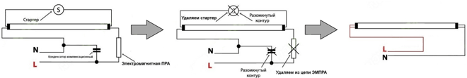
The first option requires direct power supply of the lamps from a 50 Hz 220 V mains. In this case, you must first remove all the elements of the ballasts: the electronic unit or the elements of the electromagnetic ballast (starter, choke, etc.). The power consumption of the lamp will be the sum of the total power of the LED lamps.
Procedure:
- Remove fluorescent lamps.
- Remove the old electronic circuit: a) remove the electronic control gear unit; b) remove the starters and remove the ballast from the electrical circuit, disconnect the capacitor, if any.
- Insert LED bulbs.
- Turn on the power.
Connection diagram for direct 220V LED lamp

After removing the ballasts, the lamps should look something like the photo below (the lamp was converted into two lamps 1200 mm long). Use terminals to connect contacts. 
Fluorescent lamp type Arctica 2x36 1200mm disassembled from the back side after removing all the ballast elements for connecting 220V LED lamps.
2. Connecting lamps to AC 110V :
The second option implies that the electromagnetic ballast remains in the circuit, only the starter is removed, such LED lamps are designed to supply a voltage of 110 V. With this connection, the power consumption of the lamp is the sum of the total power of the LED lamps and the power consumed by the remaining ballast. In this option, more electricity will be consumed than in the first, which means the saving effect will be less. In addition, it is necessary to first determine exactly what type of ballast is installed in the luminaires.
Procedure:
- De-energize the lamp to avoid electric shock.
- Remove fluorescent lamps.
- Remove the starters, leave the ballast (or replace the starters with special ones for LED lamps).
- Insert LED Bulbs
- Turn on the power.
Swivel base. What else you should pay attention to:
Lamps have sockets installed in different ways: horizontally, vertically, and sometimes at an angle. Since fluorescent lamps shine 360°, it does not matter to them how to install the lamp in the socket. But LED lamps have a directional luminous flux, so you should pay attention to the location of the slot for the socket in the lamp base, otherwise it may turn out that the LED lamp shines sideways rather than downwards. The most universal in this case is the swivel base: it fits any lamps. 

LED lamp sockets: a) non-rotating b) rotating.
We hope that our instructions helped you choose and connect LED lamps correctly, and now you take full advantage of all the advantages of modern LED lighting.
