This 3-channel DMU is very easy to manufacture, but has some disadvantages. This is, firstly, a large required input signal level, secondly, a low input impedance, and thirdly, a sharp blinking of the lamps caused by the lack of compression and the simplicity of the filters used. But for beginner radio amateurs, the scheme will be just right.

The flashes are controlled by thyristors. They can be placed in the KU202 series with the letters k, l, m, n. Of course, it’s better to take ones like those in the diagram. Power supply from 220V network. Each channel is adjusted using variable resistors. The circuit does not require any configuration; it works immediately after proper assembly. When working with color music, keep in mind that you need a fairly large music signal.

Transformer TP1 is made on a Ш16x24 core made of transformer steel. Winding I contains 60 turns of PEL 0.51 wire. Winding II - 100 turns PEL 0.51. Any other small-sized transformer (for example, from transistor receivers) with a ratio of turns in the windings close to 1:2 can be used. Thyristors must be installed on heat sinks if the total lamp power per channel exceeds 200 W.
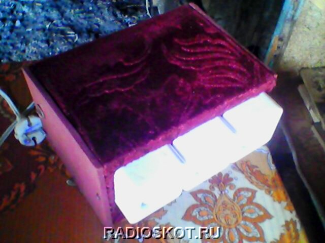
Assembled and checked. Works very well. Here is the device itself in the case:

This is the arrangement of elements inside the box that I chose. It is better to turn it on via a diode bridge. It's cheap. But I think it’s not this that’s important to a radio amateur, but the repetition of the device itself. Even a beginner can solder the circuit. The finished color music device operates without interference, and does not strain the thyristors for a long time. They don't even heat up. Author of the material: Max.
To assemble LED color music with your own hands, you need to have basic knowledge of electronics, be able to read schematics and work with a soldering iron. In the article we will look at how LED color music works, the basic working diagrams on the basis of which you can assemble ready-made devices yourself, and at the end we will step-by-step assemble the finished device using an example.
On what principle does color music work?
Color music installations are based on the method of frequency conversion of music and its transmission, through separate channels, to control light sources. As a result, it turns out that depending on the basic musical parameters, the operation of the color system will correspond to it. This trailer is the basis for the scheme for assembling color music on LEDs with your own hands.
Typically, at least three different colors are used to create color effects. It can be blue, green and red. Mixed in different combinations, with different durations, they can create an amazing atmosphere of fun.
LC and RC filters are capable of separating the signal into low, medium and high purity; they are the ones that are installed and configured in a color music system using LEDs.
Filter settings are set to the following parameters:
- up to 300 Hz for a low-pass filter, usually its color is red;
- 250-2500 Hz for medium, color green;
- everything above 2000 Hz converts into a high-pass filter, as a rule, the operation of the blue LED depends on it.
The division into frequencies is carried out with slight overlap, this is necessary to obtain different color shades during operation of the device.
The choice of color in this color music scheme is not important, and if you wish, you can use LEDs of different colors at your discretion, change places and experiment; no one can prohibit it. Various frequency fluctuations combined with the use of a non-standard color scheme can significantly affect the quality of the result.
The circuit parameters such as the number of channels and their frequency are also available for adjustment, from which we can conclude that color music can use a large number of LEDs of different colors, and it is possible to individually adjust each of them in frequency and channel width.
What is needed to make color music
Resistors for color music installations, produced in-house, can only be used constant, with a power of 0.25-0.125. Suitable resistors can be seen in the figure below. The stripes on the body indicate the resistance value.

The circuit also uses R3 resistors, and trimmers R - 10, 14, 7 and R 18, regardless of type. The main requirement is the ability to install on the board used during assembly. The first version of LED color music was assembled using a variable-type resistor designated SPZ-4VM and imported trimmers.

As for capacitors, you need to use parts with an operating voltage of 16 volts, no less. Can be any type. If you have difficulty finding capacitor C7, you can connect two smaller capacitors in parallel to obtain the required parameters.
The capacitors C1, C6 used in the LED color music circuit must be capable of operating at 10 volts, respectively C9–16V, C8–25V. If, instead of old Soviet capacitors, you plan to use new, imported ones, then it is worth remembering that they have a difference in designation; you need to determine in advance the polarity of the capacitors that will be installed, otherwise you can confuse and damage the circuit.

To make color music, you will also need a diode bridge with a voltage of 50V and an operating current of about 200 milliamps. In cases where it is not possible to install a ready-made diode bridge, you can make it from several rectifier diodes; for convenience, they can be removed from the board and mounted separately using a smaller board.

The parameters of the diodes are selected similarly to the diodes used in the factory version of the bridge.
LEDs should be red, blue and green. For one channel you will need six of them.
Another necessary element is a voltage stabilizer. A five-volt stabilizer is used, imported, with article number 7805. You can also use 7809 (nine-volt), but then you need to exclude resistor R22 from the circuit, and instead put a jumper connecting the negative bus and the middle terminal.
You can connect the color music system to the music center using a three-pin jack connector.

And the last thing you need to have for assembly is a transformer with suitable voltage parameters.
General diagram for assembling color music, which uses the parts described in the photo below.

Several working schemes
Below we will propose several working schemes for LED color music.
Option #1
Any type of LED can be used for this circuit. The main thing is that they are super bright and different in glow. The circuit works on the following principle: the signal from the source is transmitted to the input, where the channel signals are summed and then sent to a variable resistance. (R6, R7, R8) Using this resistance, the signal level for each channel is adjusted, and then sent to the filters. The difference between filters is in the capacity of the capacitors used to assemble them. Their purpose, as in other devices, is to transform and purify the sound range within certain boundaries. These are high, mid and low frequencies. For adjustment, adjustment resistors are installed in the color music circuit. Having gone through all this, the signal goes to a microcircuit that allows you to install various LEDs.

Option No. 2
The second version of LED color music is distinguished by its simplicity and is suitable for beginners. The circuit involves an amplifier and three channels for frequency processing. A transformer is installed, which can be dispensed with if the input signal is sufficient to open the LEDs. As in similar circuits, adjustment resistors are used, designated as R4 - 6. Any transistors can be used, the main thing is that they transmit more than 50% of the current. Essentially, nothing more is required. The circuit can be improved, if desired, to obtain a more powerful color and music installation.

Step-by-step assembly of the simplest color music model
To assemble a simple LED color music you will need the following materials:
- LEDs measuring five millimeters;
- wire from old headphones;
- original or analogue of transistor KT817;
- 12 volt power supply;
- several wires;
- a piece of plexiglass;
- glue gun
The first thing you need to start with is to make the body of the future color music from plexiglass. To do this, it is cut to size and glued together with a glue gun. It is better to make the box rectangular. The sizes can be adjusted to suit you.

To calculate the number of LEDs, divide the adapter voltage (12V) by the operating LEDs (3V). It turns out we need to install 4 LEDs in the box.
We strip the cable from the headphones, there are three wires in it, we will use one for the left or right channel, and one for the common one.

We don't need one wire and it can be insulated.
The diagram of a simple LED color music looks like this:

Before assembly, we lay the cable inside the box.
LEDs have polarity, so when connecting, it must be taken into account.
During the assembly process, you should try not to heat the transistor, as this can lead to its breakdown, and pay attention to the markings on the legs. The emitter is designated as (E), base and collector, respectively (B) and (K). After assembly and inspection, you can install the top cover.

Ready-made version of LED color music
In conclusion, I would like to say that assembling color music using LEDs is not as difficult as it might seem at first. Of course, if you need a device with a beautiful design, then you will have to spend a lot of time and effort. But to make simple color music for informational or entertainment purposes, it is enough to assemble one of the diagrams presented in the article.
This LED color music is suitable for those who listen to music on the computer. It can be placed inside the case and it will be illuminated to the beat of the music.
The color music scheme is very simple and does not present any difficulties.
 Required components:
1. 4 LEDs (any color) 3mm
2. P2 plug
3. 2 position switch
4. Bipolar transistor TIP31
5. The box (if needed) can also be placed directly in the computer case
6. Soldering iron
7. Cable
 We connect 4 LEDs to +12 V of the computer, connect the anode to a 2-position switch, which in turn is connected to a TIP31 bipolar transistor. We connect the two unused ends of the transistor directly to the terminals of the plug for headphones or speakers P2.
We install all assembled components in a box (box), or directly into the computer case - this is up to everyone’s own discretion. We made holes for the LEDs, switch and plug.

Installation of LED color music in a box
Let's connect the LEDs, transistor and switch
1 of 2

Connecting LEDs

General assembled view with transistors
Next comes the most interesting part. It is necessary to solder the LEDs together, the transistor and the switch. From the photographs it is clear without words. The only thing is that we had to select the length of the conductors so that they would fit in the box.
We connect the common negative from the LEDs to the middle contact of the switch. From the switch, one of the positions is connected to the middle pin of the transistor, connect the second position according to the color music diagram that we presented above.
Installation of wires to plug P2
Final stage
1 of 2

Installation of diode color music circuit

Soldered plug
If we disassemble the headphone plug, we can see three connectors inside - left and right channels, ground. We connect one of the channels to the left pin of the Tip31 transistor. If P2 is connected through the left channel and it does not “beat” with the computer output, then our circuit will not work. Therefore, immediately decide correctly or experiment. Ground (usually a long connector) should be connected to the right pin of the transistor.
One of the switch pins should be connected to ground from the transistor. With this connection, the LEDs will start blinking if there is any signal at the output. If there is no signal coming from connector P2, if there is a signal on the other side, they will light up constantly.
We mount everything in the box, connect it and check its functionality.
A very simple three-channel RGB color music on LEDs does not contain scarce or expensive components. All elements can be found in anyone, even the youngest radio amateur.
The operating principle of color music is classic and has truly become the most popular. It is based on dividing the sound range into three sections: high frequencies, mid frequencies and low frequencies. Since color music is three-channel, each channel monitors its frequency limit and when its level reaches the threshold value, the LED lights up. As a result, when playing music, a beautiful lighting effect is created when LEDs of different colors blink.
Simple color music scheme
Three transistors - three channels. Each transistor will act as a threshold comparator and when the level exceeds 0.6 Volts, the transistor opens. The transistor load is an LED. Each channel has its own color.In front of each transistor there is an RC circuit that plays the role of a filter. Visually, the circuit consists of three independent parts: the upper part is the high-frequency channel. The middle part is the mid frequency channel. Well, the lowest channel in the diagram is the low-frequency channel.
The circuit is powered by 9 Volts. The input receives a signal from headphones or speakers. If the sensitivity is not enough, then you will need to assemble an amplifier stage on one transistor. And if the sensitivity is high, then you can put a variable resistor at the input and use it to regulate the input level.
You can take any transistors, not necessarily KT805, here you can even install low-power ones like TK315 if the load is only one LED. In general, it is better to use a composite transistor like KT829.
You can also take all the other components of the circuit there.
Assembly of color music
You can assemble the color music using wall-mounted mounting or on a circuit board, as I did.No setup is needed, it’s assembled, and if all the parts are suitable, everything works and blinks without problems.

Is it possible to connect an RGB LED strip to the input?
Of course you can, to do this we connect the entire circuit not to 9 V, but to 12. In this case, we throw out the 150 Ohm quenching resistor from the circuit. We connect the common wire of the tape to plus 12 V, and distribute the RGB channels among the transistors. And, if the length of your LED strip exceeds one meter, then you will need to install transistors on radiators so that they do not fail due to overheating.Color music at work
Looks quite beautiful. Unfortunately, this cannot be conveyed through pictures, so watch the video.Today we were in the Auchan store and bought MCM color music for home disco. It was simply impossible to resist: at the regular price of 1,500 rubles, the device was sold for 399! Of course, this shrill Chinese contraption can't even remotely compare to this a color and music installation that operates according to very specific laws. The purchased product is rather a simple “flashing light”. However, if you just need to organize a small party at home without going into details of the operating principle, then it will be quite suitable for organizing lighting effects. At least my 4-year-old son was absolutely delighted with it. In this article I would like to leave review about color music MCM and meditate a little on the topic of color music installations as such.
Previously, color music was made by hand
During the Soviet era, there was a lot of tension with good audio equipment. Of course, there were first-class stereo tape recorders, for example, Rostov-105. Their sound quality was excellent, especially if you record music from a good source onto German Agfa magnetic tape at a speed of 19 (centimeters per second).

Reel-to-reel stereo tape recorder Rostov 105. Photo from the Internet
Alas, all this was very expensive and practically inaccessible to ordinary Soviet workers and employees. Well, judge for yourself, with a salary of 150 rubles a month, buying a stereo recorder for 400 rubles was an unaffordable luxury. They could have easily “taken it apart” at the trade union committee and, at best, made it look like it. At worst - a Komsomol or party card "on the table." But we also had to buy speakers, which were also not cheap.
Approximately the same situation was with color and music installations. There were almost no factory-made home appliances, and large professional ones were again simply unaffordable in price.
At that time, the vast majority of “color music” were assembled at home by hand using radio components purchased at the “Young Technician” store according to schemes published in the magazine “Technology for Youth” or “Model Designer”.
It would never occur to modern youth to make color music with their own hands. After all, you can go to the store and buy ready-made ones. Or even download a program from the Internet and turn your computer monitor into an excellent color and music screen, which will also have a bunch of different settings.
Almost no one today “etches” printed circuit boards in a special solution, exchanges or otherwise obtains scarce radio components, solders circuits, or racks their brains over the design of the light part of the device.
But at one time it was a special chic to make your own color music, which not only would not explode when turned on for the first time, but would work, and in strict accordance with all the rules. By the way, about the rules.
How real color music works
Now many people don’t even know this. And before, real radio amateurs and specialists in such devices had a great idea of what was what. The fact is that multi-colored light bulbs in color music should not blink chaotically, not when they want, but in exact accordance with the frequency response of the music being played.
Let's look at this with an example, if you're at all interested.
Let's take some song and try to sort it into frequencies.
What "booms" is the low sound frequencies. Their sources can be a drummer, a bass guitar, and modern synthetic sounds that make the dishes rattle in the sideboard. In acoustic systems, the largest speakers are responsible for high-quality reproduction of low frequencies. So, when low sound frequencies appear in the general spectrum, red lamps should light up in the color music installation. Why? Simply because red is also the lowest frequency color in the visible light range. When creating the concept of a color music installation, the inventors decided to make sure that low-frequency sound was accompanied by low-frequency light.
Thus, if you imagine an ordinary classic rock or pop composition, then flashes of red color indicated the rhythm of the drummer and the bass intro.
At the other pole is the high-frequency component of music. These are all whistling sounds, like hitting cymbals in a drum kit. When a high-frequency component appears in the general musical background, the blue lamps should flash. Again "why"? Because blue is one of the highest frequencies in the visible range. Violet would have been even more suitable from the point of view of frequency response, but for some reason the inventors settled on blue. That's how it happened.
Anything within the mid range should be accompanied by green flashes.
Thus, in real color music, the sound is, as it were, colored and visualized in full accordance with the frequency characteristics.
From this point of view, modern color music installations often look like simple flashing lights, which either implement the so-called “running light” or simply randomly turn on lamps of one color or another. Although there are pleasant exceptions today.
How real color music works
I dare to show you an electrical circuit diagram. Alas, only specialists can understand it at first glance, so we will have to explain something:

images from the Internet
So on the right are the lamps. You recognized them. These are ordinary light bulbs that are screwed into chandeliers. Moreover, previously it was impossible to simply go to the store and buy red, green and blue lamps. Therefore, at that time, ordinary or, even better, matte lamps of the required power were purchased. Then their flasks had to be painted.
The most accessible paint was ordinary ink from ballpoint pens. We took the rod and carefully removed the metal tip with the ball. Then they blew ink onto the paper. And then they started painting the light bulbs. And not with brushes or sponges - after all, the ink was quite thick - you had to paint with your finger. Yes Yes! They dipped their index finger into a squeezed-out ink blot on paper and began to spread the ink across the surface of the light bulb. When someone came to school the next morning with multi-colored fingers, we immediately understood the reason and asked: “Well, did it work?”
Now you can go to an electrical goods store and buy everything you need. And then there were different times. We had to use what was at hand. Now it already looks funny and absurd. But previously this was almost the only way to get colored lamps.
To the left of the light bulbs in the diagram are thyristors - the most scarce and expensive parts of color music. They made it possible to transfer electricity from the socket to the light bulbs. They were like shutters, which "opened" on command from the rest of the electrical circuit and supplied voltage from the socket to the corresponding lamp. The lamp lit up while the thyristor was “open”. The thyristors became very hot during operation, so they had to be installed on radiators for additional cooling.
The rest of the circuit, consisting of resistors (red) and capacitors (silver), was responsible for decomposing the input signal from the tape recorder into frequency components and opening the thyristor gates (lighting the light bulbs) when a signal of a certain frequency range appears at the input.
If interested, look at the colored wires. It will become clear which part of the circuit is responsible for the low-frequency (red), mid-frequency (green) and high-frequency (blue) signal.
A separate variable resistor (at the top of the circuit) made it possible to adjust the sensitivity of the circuit. The fact is that different tape recorders and players had different signal power at the linear output. Therefore, it was impossible to do without this possibility of smooth adjustment. Otherwise, it could happen that all the lamps would be on all the time without any blinking if the signal was strong, or, on the contrary, would not turn on at all if the input signal was weak.
Now I would like to apologize to real professionals in radio engineering for such a free explanation of the principle of operation of color music. Do not worry. Most readers won't pay any attention to it anyway. I was just trying to explain it in a way that everyone could understand.
Thus, real color music consisted of two parts:
- control unit - the electrical circuit itself
- light block - lamps
When relatively inexpensive household installations went on sale, they looked, for example, like this:

images from the Internet
Color music on starters
You will laugh, but in those distant Soviet times, not everyone was able to get thyristors. That was the shortage.
But I still wanted to have color music!
And then another solution came to the aid of those suffering: a color and music installation with electric starters.
In fact, this was originally a flashing light circuit for a garland. Now they are sold with built-in flashers, which, moreover, contain several different programs. And then the Christmas tree garland was simply plugged into an outlet and burned constantly (like a stupid thing).
All self-respecting radio amateurs at that time knew how to make a very simple flasher. Here is her diagram:

images from the Internet
And this is what the device looked like in real life:

images from the Internet
It's simple. No scarce parts. There are only two elements - a starter (they are used in lamps with fluorescent lamps) and a capacitor. The garland was plugged into a socket on the device, and the device itself was plugged into the network. The Christmas tree garland began to blink. Moreover, the blinking was chaotic both in duration and frequency.
Thus, without much hassle and expense, a device was obtained that could be used to organize home (and not only home) parties. The lamps turned on chaotically and completely independently of each other. There were moments when they burned all together, sometimes in pairs, sometimes just one. Sometimes they all turned off at the same time and the room was completely dark for a moment.
Alas, there was no connection whatsoever with the frequency characteristics of the music. Even during a pause between songs, the device continued to flash regularly. But... you know, it was very funny to follow the random blinking and compare it with the music playing. At some moments there were random coincidences with the rhythm or with the same frequency characteristic. But, of course, this was the exception rather than the rule.
Of course, this was not real color music, but in the absence of fish, as they say, even a crab is a fish.
30 years have passed since those ancient times. Now anyone can simply go to a store (an ordinary supermarket) and buy a color and music installation for a certain amount. Of course, this is very cool. It’s just a little pity that modern boys can no longer feel that indescribable happiness when the color music made by your hands suddenly “came to life” and began to work, and exactly the way it SHOULD!
Color music MCM with microphone
Let's go back to today. As I already said, the reason for this article was the purchase color and music installation MCM.
I can't speak for everyone, but if something like this fell into my hands at the age of 16, I would be one of the happiest people. Then there were slightly different values: imported factory-made color music with real color lamps and a microphone for analyzing the sound of music would have created a real sensation among fellow boys! Judge for yourself:


In fact, there is everything you need here: three lamps, and not painted with fingers dipped in ink from a ballpoint pen, but real ones, made of colored glass.
There is a control unit with a tempo and sensitivity regulator.
There is a microphone that picks up the music and transmits it to an electronic circuit that should essentially operate the same way as the thyristor circuit above.
In addition, the design of MSM color music was very different from the homemade boxes in which radio amateurs in the old days packaged their products.

As you can see, the color music body can be disassembled into individual components. True, placing them in different corners of the room simply won’t work - the wires are short. But the collapsible body already gives some room for maneuver, and the wires, if necessary, can be extended.
I wonder what it says on the box LED color and music installation. An obvious lie. The design uses conventional 60-watt incandescent lamps. Therefore, during operation, the device begins to pose some danger to others. I can imagine what will happen if some tipsy guest “loses control” and comes into contact with the fiery lamp of the color music :).
How does MSM color music work?
Rather than describe for a long time, it is better to show. In this video, color music first works in the “running fire” mode, and then I turn on the microphone and a certain “reaction” to the sounding music appears. How much it can satisfy you - decide for yourself.
Conclusion
For real radio engineering enthusiasts, not to mention professionals, MCM color music is a real mockery of the best engineering feelings. With its free interpretation of the frequency range and clumsy response to playing music, the device can drive experienced users into a frenzy.
Therefore, if you want to enjoy the exact match of sound and color images, then I do not recommend buying this product. The best solution for you is to assemble the device yourself. You will get real pleasure from both the assembly process and the work of your color music.
If you just need to highlight a children’s party or a completely adult corporate event, then a couple of these devices will cope with the task. Everyone will have a lot of fun... there is only one BUT.
If a real engineer turns out to be at the holiday, I don’t mean by his diploma, but by his essence, he will leave the holiday upset and then, perhaps, even get sick. Because in his view, MCM color music will be a real outrage against the very concept of color music devices. There is certainly some humor in this phrase. However, I remember an incident when I myself left a concert only because two guitars were “not in tune” - that is, one string of one of the guitars was tuned incorrectly. No fun! One frustration!
So, I told you everything, showed you, and you decide whether to buy such color music.
